AVG7 module adjustment procedures
To adjust the f
requency response
Preparation
To perform the frequency response adjustment, you must first remove the top
coveroftheT
G8000 mainframe. (See page 2-25, To p cover.)
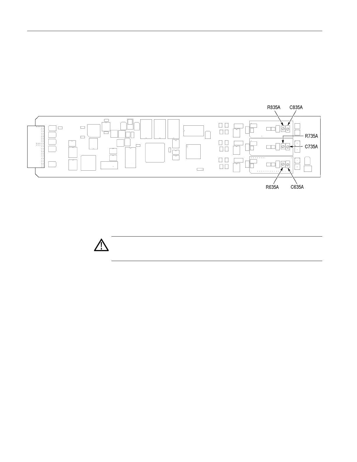
After you have removed the top cover, find the v ariable resistors and capacitors on
the AVG7 mod
ulecircuitboard. (SeeFigure6-6.)
Figure 6-6: Location of the variable resistors and capacitors for the frequency response adjustment
Procedure
WARNING. To avoid serious injury, do n ot touch exposed connectors or
components when operating the TG8000 mainframe with the top cover removed.
Dange
rous potentials exist at several points w ithin the TG8000 mainframe.
1. Use the two 75 Ω BNC cable, peak detector head, and BNC female-to-female
conn
ector to connect the upper CH 1 connector on the AVG7 module to the
+INPUT connector on the peak detector amplifier. (See Figure 6-7.)
2. Use
the 75 Ω BNC cable to connect the OUTPUT connector on the peak
detector amplifier to the CH 1 input connector on the oscilloscope. (See
Figure 6-7.)
3. Use the 75 Ω BNC cable and the 75 Ω feed-through termination to connect the
BLACK 1 connector on the test signal generator to the CH 2 input connector
on the oscilloscope. (See Figure 6-7.)
6–10 TG8000 Multiformat Test Signal Generator Service Manual

 Loading...


