AVG7 module adjustment procedures
9. Adjust C804B an
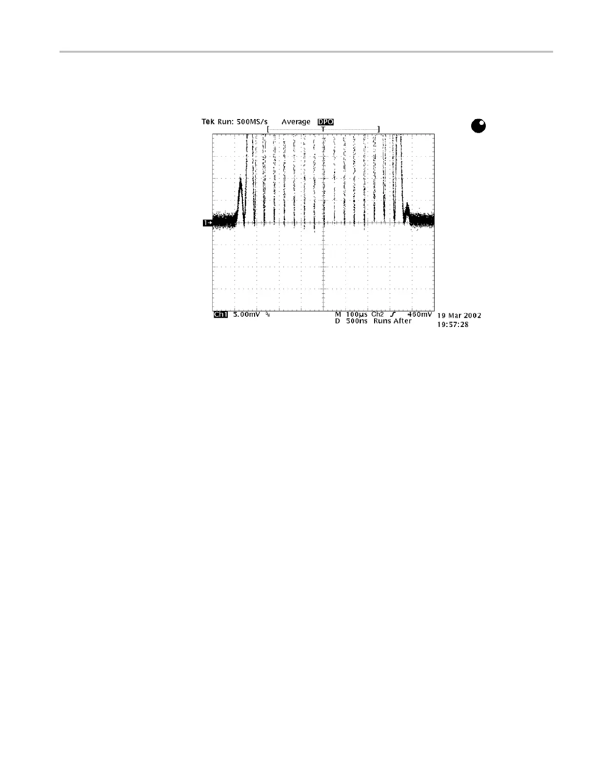
d C835A so that the baseline of the modulated 20T pulse
signal is flat. (See Figure 6-5.)
Figure 6
-5: Adjusting the baseline of the modulated 20T pulse signal
10. Move the
BNC cable from the upper C H 1 connector to the upper CH 2
connector on the AVG7 module.
11. Adjust
C704B and C735A so that the baseline of the modulated 20T pulse
signal is fl at.
12. Move t
he BNC cable from the upper CH 2 connector to the upper CH 3
connector on the AVG7 module.
13. Adju
st C604B and C635A so that the b aseline of the modulated 20T pulse
signal is fl at.
TG8000 Multiformat Test Signal Generator Service Manual 6–9

 Loading...


