HDVG7 module adjustment procedures
Table 13-1: Equipment required for the HDVG7 module adjustment procedures (cont.)
Item No. Minimum requirement Recommended equipment
1 m (3 ft.) BNC to BNC 50 Ω
cable
1 Tektronix part number 012-0057-01
75 Ω precision terminator
1
75 Ω ±0.1%
Tektronix part number 011-0102-03
BNC T connector
1 Tektronix part number 103-0030-00
BNC female to dual banana
adapter
1 Tektronix part number 103-0090-00
To adjust the output level
Prepara
tion
To perform the output level adjustment, you must first remove the top cover of
theTG8000mainframe. (Seepage2-25,Top cover.)
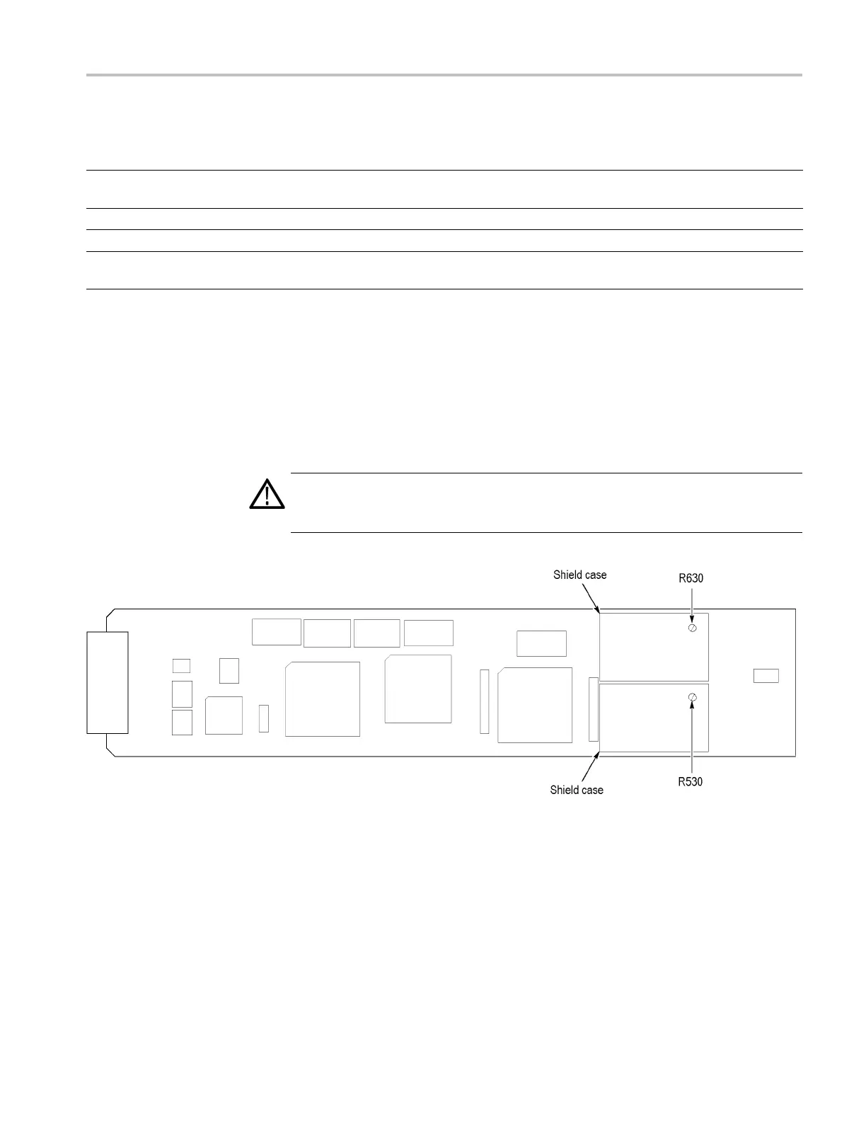
After you have removed the top cover, find the v ariable resistors on the HDVG7
circuit board. (See Figure 13-1.)
WARNI
NG. To avoid s erious injury, do not touch exposed connectors or
components when operating the TG8000 mainframe with the top cover removed.
Dangerous potentials exist at several points within the TG8000 mainframe.
Figure 13-1: HDVG7 module circuit board
TG8000 Multiformat Test Signal Generator Service Manual 13–3

 Loading...


