ATG7 module adjustment procedures
To adjust the o
utputoffsetandgain
Preparation
To perform the output offset and gain adjustment, you must first remove the top
cover of the T
G8000 mainframe. (See page 2-25, Top cove r.)
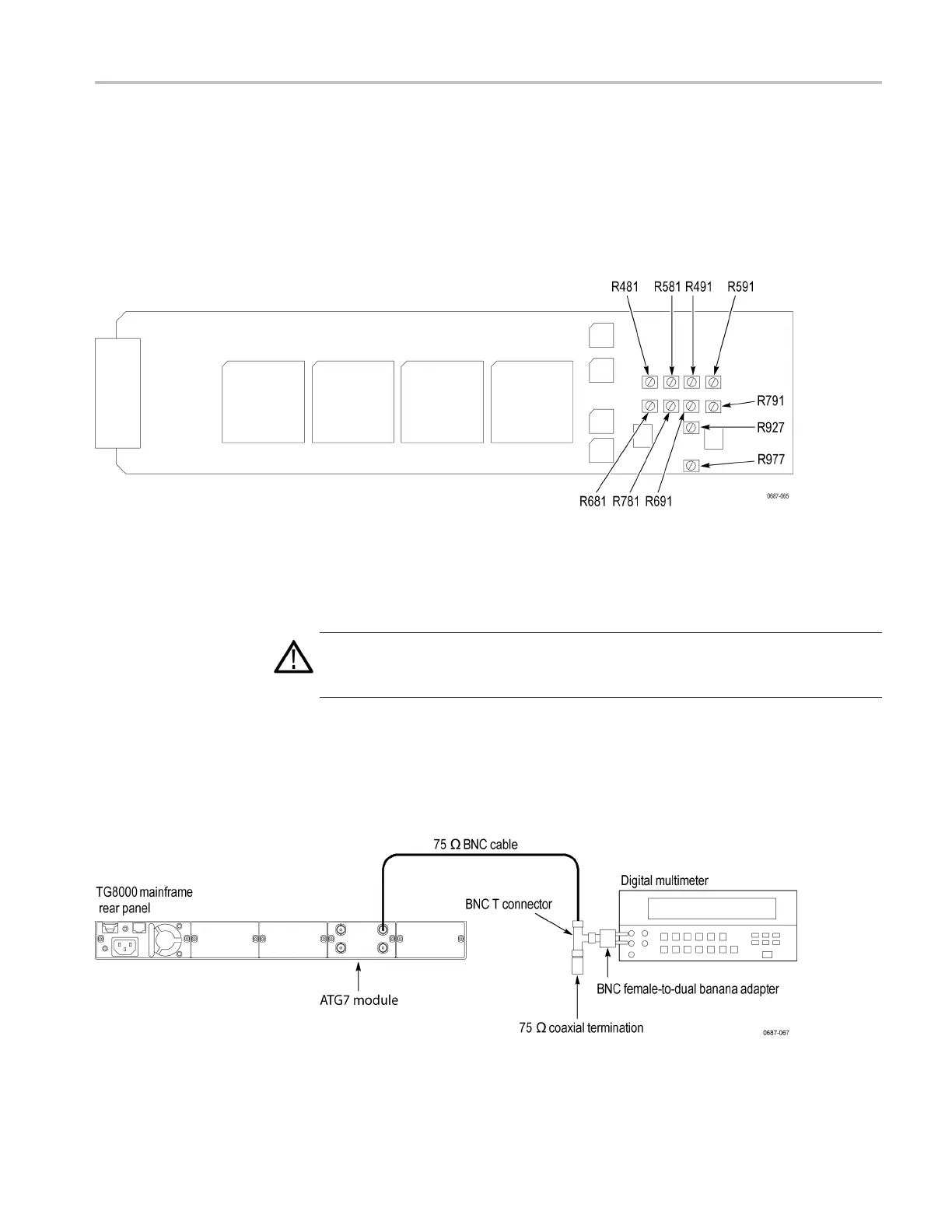
After you have removed the top cover, find the variable resistors on the ATG7
circuit boa
rd. (SeeFigure5-1.)
Figure 5-1: ATG7 module circuit board
Procedure
WARNING. To avoid serious injury, do not touch exposed connectors or
components when operating the TG8000 mainframe with the top cover removed.
Dangerous potentials exist at several points within the TG8000 mainframe.
1. Use the 75 Ω BNC cable, BNC T connector, 75 Ω coaxial terminator, and
BNC female-to-dual banana adapter to connect the BLACK 1 connector on
the ATG7 module to the input connector on the digital multimeter. (See
Figure 5-2.)
Figure 5-2: Equipment connection for adjusting the ATG7 output offset and gain
TG8000 Multiformat Test Signal Generator Service Manual 5–3

 Loading...


