NetSure
™
Control Unit (NCU)
User Manual, UM1M830BNA
Spec. No: 1M830BNA, 1M830DNA Code: UM1M830BNA
Model No: M830B, M830D Revision M, May 12, 2017
System Status Area
System status is displayed in this area and consists of a Power System tab and a General Status tab.
Temperature Readings
The temperature sensor set as “Ambient Temp Sensor” (Settings Menu / System Tab) is the sensor which displays the ambient
temperature on the Power System tab.
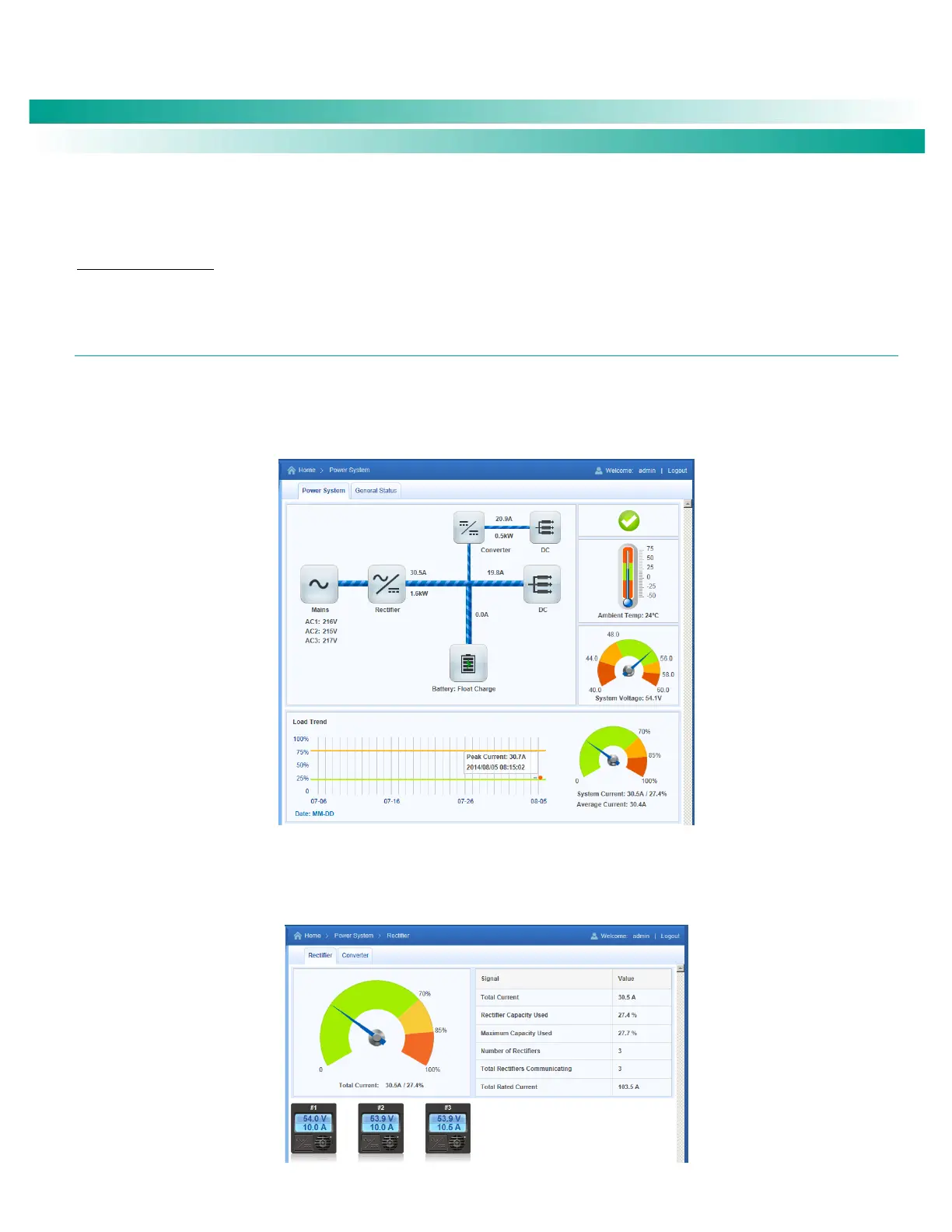
POWER SYSTEM TAB
The Power System tab displays power system status in a graphical block diagram format. This includes status of the input power,
modules (i.e. rectifiers, solar converters, converters), DC equipment, and battery. Also displayed are alarm status, ambient temperature,
output voltage, output current, average current, and a load trend chart.
Figure 26. Power System Tab
The power system status area is User interactive. Clicking on the various icons will take you to that devices status Web page. For
example, clicking on the rectifier module icon opens the following Web page. This topic is further explained in the next section.
Figure 27. Rectifier Module Status Web Page

 Loading...


