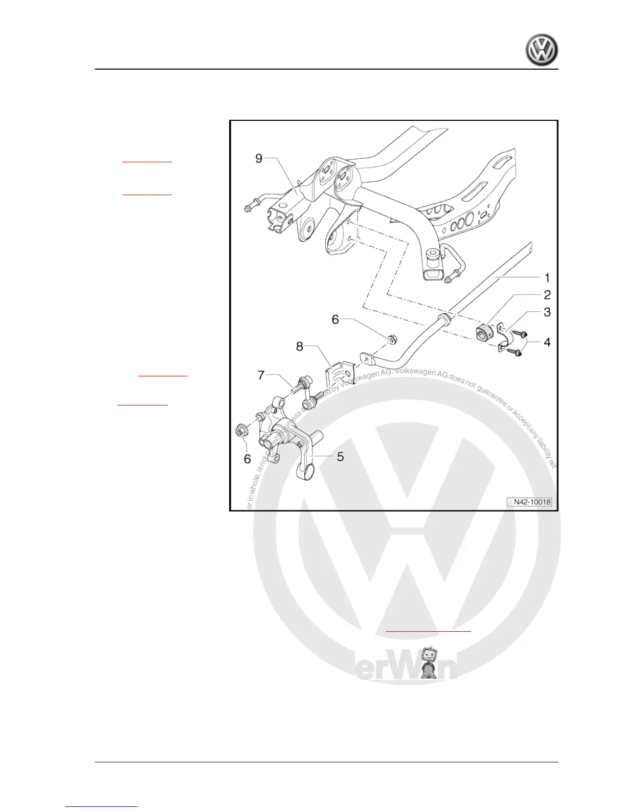
6 Assembly overview: anti-roll bar (front-wheel drive)
1 - Anti-roll bar
❑ Note different versions
of running gear
⇒ page 317 , vehicle
data plate
❑ Removing and installing
⇒ page 179
2 - Bush
❑ Always renew bushes
on both sides of the ve‐
hicle.
3 - Clamp
4 - Bolt
❑ 25 Nm +45° further
❑ Tighten evenly.
❑ Always renew after re‐
moving
❑ Always tighten threaded
connections in unladen
position:
Golf ⇒ page 136
Golf Plus, CrossGolf
⇒ page 138
5 - Wheel bearing housing
6 - Nut
❑ 45 Nm
❑ Self-locking
❑ Always renew after re‐
moving
7 - Coupling rod
❑ Modified coupling rod
for model year 2004
During production start up, a change was made from coupling rods with two ball joints to coupling rods with
one ball joint and one bonded rubber bush. The end with the bonded rubber bush is bolted to the anti-roll bar.
A mixed installation is not permissible.
❑ Connects anti-roll bar to trailing arm and wheel bearing housing
8 - Shield
❑ Only in vehicles having two ball joints in coupling rod. For vehicles with new coupling rod (one ball joint
and one bonded rubber bush), no shield is installed. See also ⇒ Item 7 (page 179) .
9 - Subframe
6.1 Removing and installing anti-roll bar
Special tools and workshop equipment required
Golf 2004 ➤ , Golf Plus 2005 ➤
Running gear, axles, steering - Edition 08.2009
6. Assembly overview: anti-roll bar (front-wheel drive) 179
 Loading...