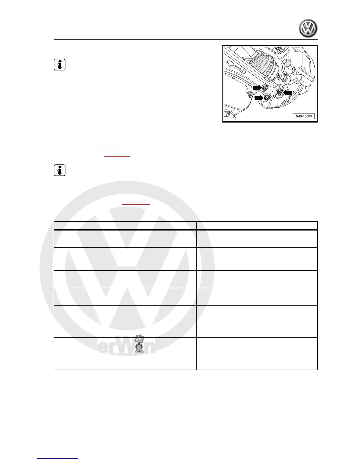
– Bolt swivel joint to suspension link -arrows-.
Note
Ensure boot is not damaged or twisted.
– Place inner joint of drive shaft in position and tighten bolts di‐
agonally to 10 Nm.
– Tighten multi-point socket-head bolts diagonally to the speci‐
fied torque.
– Attach lower noise insulation ⇒ Rep. Gr. 50 ; Assembly over‐
view - noise insulation .
– Tighten drive shaft bolt at wheel hub:
♦ Hexagon bolt ⇒ page 77
♦ Twelve-point bolt ⇒ page 78
Note
During this step, vehicle must not be standing on its wheels or
wheel bearing will be damaged.
– Install wheel and tighten ⇒ page 288 .
Specified torques
Component Specified torque
Swivel joint to cast steel suspension link
♦ Use new nuts
60 Nm
Swivel joint to sheet steel or forged aluminium suspension
link
♦ Use new nuts
100 Nm
Drive shaft to wheel hub “hexagon bolt”
♦ Use new bolt
200 Nm +180°
Drive shaft to wheel hub “12-point bolt”
♦ Use new bolt
70 Nm + 90°
Drive shaft to flange shaft on gearbox “M8 multi-point sock‐
et”
♦ Use new bolts
♦ Use new backing plates
40 Nm
♦ Initially tighten diagonally to 10 Nm.
Drive shaft to flange shaft on gearbox “M10 multi-point
socket”
♦ Use new bolts
♦ Use new backing plates
70 Nm
♦ Initially tighten diagonally to 10 Nm.
6.4 Removing and installing left drive shaft
with (push-on) constant velocity slip joint
Special tools and workshop equipment required
Golf 2004 ➤ , Golf Plus 2005 ➤
Running gear, axles, steering - Edition 08.2009
6. Removing and installing drive shafts 81
 Loading...