5-16 OM ET18/20/24 us 1.3 * et18_20_24b510.fm
5
Hydraulic swivel unit brake:
The upper carriage’s rotation is sufficiently braked by moving the left-hand
control lever back to initial position. Moving the control lever in the
opposite direction (counteraction) brakes the upper carriage with
maximum hydraulic output.
Mechanical swivel unit brake:
A multidisc brake integrated in the rotation drive has an additional
mechanical brake effect. The brake is used to brake the swivel unit. The
upper carriage can be stopped in any position.
ISO/SAE controls (option)
Accident hazard due to modified control lever operation!
Can result in severe injury or death.
► Ensure that you know which control mode has been selected
before starting machine operation.
► Always secure the wing nut on the changeover lever of the
directional valve.
No traveling or operating the machine if the wing nut is
malfunctioning.
► Contact a Wacker Neuson service center and replace the
malfunctioning wing nut.
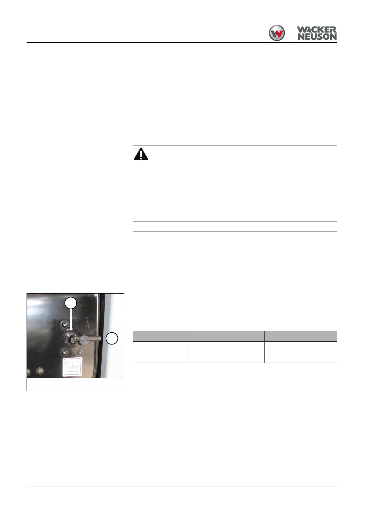
The directional valve is located at the left under the seat.
The directional valve can be switched between Operating Pattern A (ISO
controls) and Operating Pattern B (SAE controls).
The function label for the controls is affixed on the roof window.
Fig. 140: Directional valve
A
B
Wiring diagram Controls
A ISO controls Operating Pattern A
B SAE controls Operating Pattern B
 Loading...