OM ET18/20/24 us 1.3 * et18_20_24t900.fm 9-5
9
9.8 Electrical system
Electrical components
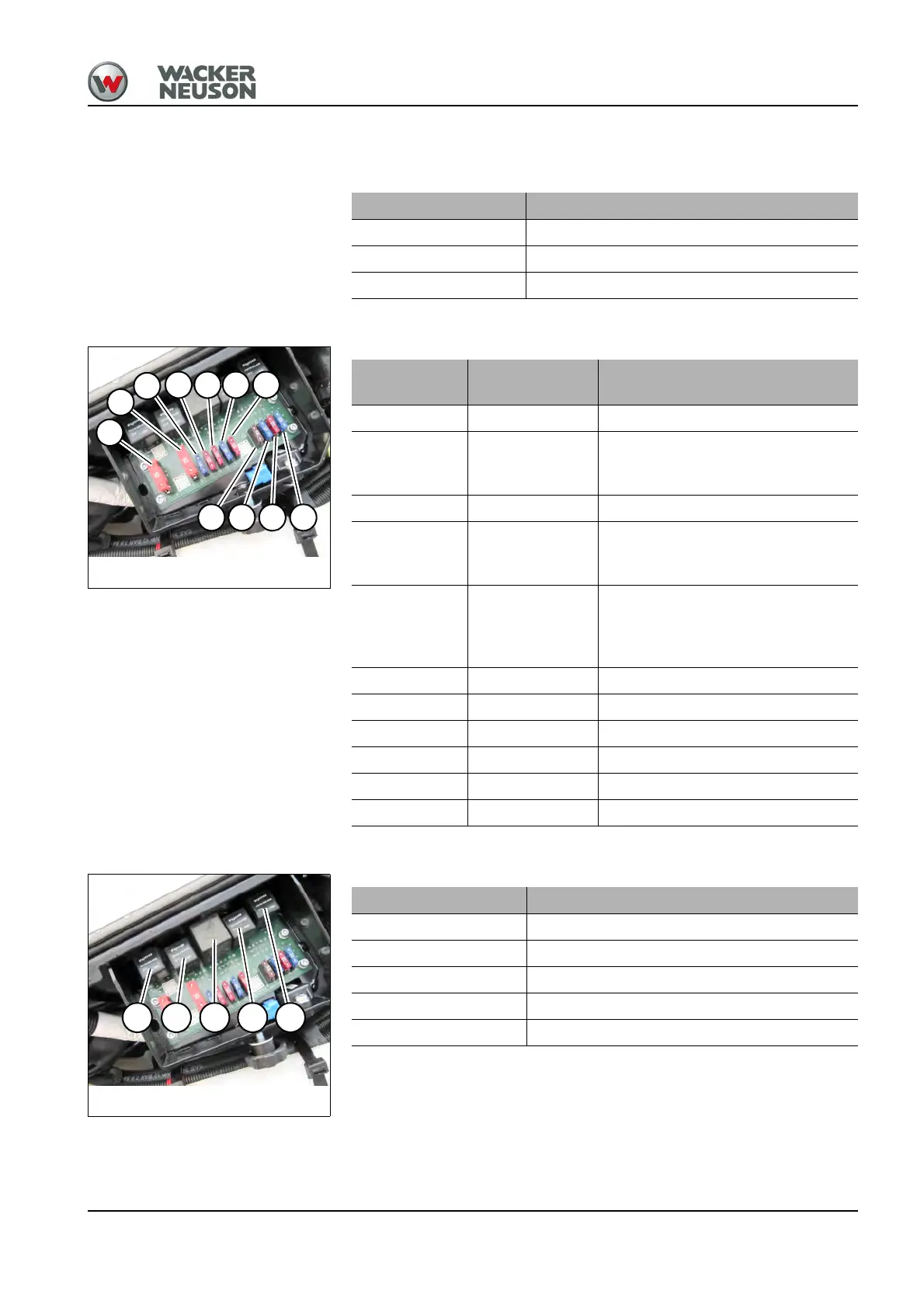
Fuses
The fuses are located behind the left-hand cover.
Relays
The relays are located behind the left-hand cover.
ET 18/ET 20/ET 24
Alternator 12 V 55 A
Starter 12 V 1.1 kW (1.5 hp)
Battery 12 V 44 Ah
Fig. 275:Fuses
F2
F1
F10
F11 F6 F9 F5
F3 F4 F7 F8
Fuses
Rated current
(A)
ET 18/ET 20/ET 24
F1 50 A Starter, cutoff solenoid, socket
F2 50 A
Starter, air-pressure sensor/output
adaptation (Yanmar 3TNV80F-
SNNS1)
F3 7.5 A Display, cutoff solenoid
F4 15 A
Valves, horn, high speed, hydraulic
quickhitch, upper carriage tilting,
automatic engine speed setting
F5 10 A
Proportional auxiliary hydraulics
(AUX I)
Proportional 3rd control circuit (AUX
II)
F6 10 A Heating, overload, traveling signal
F7 10 A Lights
F8 15 A Lights
F9 15 A Wiper, radio, interior light
F10 15 A Socket, 12 Vpower outlet
F11 10 A Rotating beacon, radio
K7 K9 K51 K58 K17
Fig. 276:Relays
Relays ET 18/ET 20/ET 24
K7 Starting relay
K9 Cutoff solenoid
K51 Idling speed
K58 High speed (2nd travel speed)
K17 Hydraulic quickhitch
 Loading...