4 Parts Replacement RJ-901C/RJ-900C Maintenance Manual
4-16
4.3 Replacement of Board Base Section Components
This section describes replacement procedures of power board assembly, main board assembly, network
interface card (NIC), and cooling fan.
CAUTION
When you handle a circuit board, do not touch any elements on it with bare hands.
Doing so may cause electrostatic discharge and damage the elements.
4.3.1 Replacing Connector Panel, Network Interface Card (NIC),
Cooling Fan
(1) Replacing NIC
1. Remove the bracket network interface card screw (tapping screw M3 × 6, S cup: 1pcs).
2. Remove the NIC from the main board and replace it.
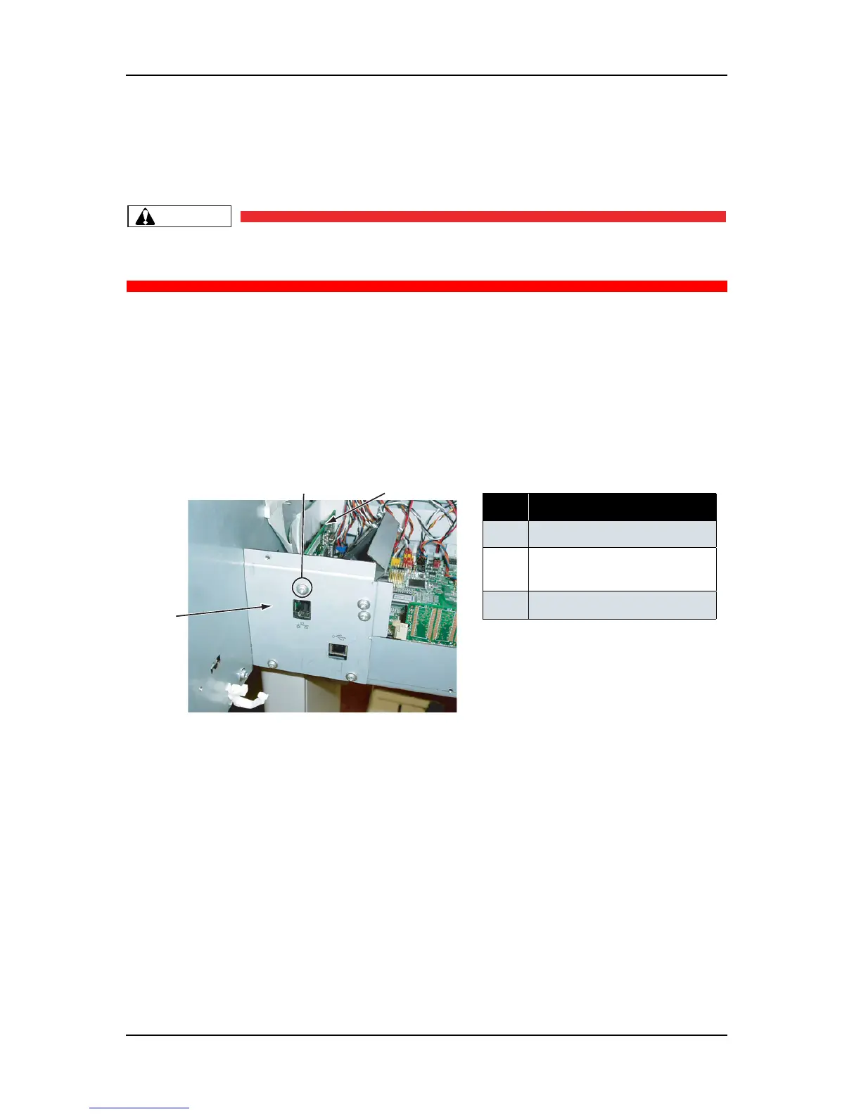
(2) Removing Connector Panel
1. Remove the cooling fan (5V) connector.
2. Remove the cooling fan (5V) cable from the clamp.
No. Part name
1 Connector panel
2
Bracket network interface card
screw
3
NIC
2
3
1
 Loading...