4 Parts Replacement RJ-901C/RJ-900C Maintenance Manual
4-18
4.3.2 Removing Board Bracket
NOTE
Before replacing the board assemblies, remove the following parts.
• Media guide R2: "4.2.7 Removing Media Guide R2" p.4-14
• Connector panel: "4.3.1 Replacing Connector Panel, Network Interface Card (NIC),
Cooling Fan" p.4-16
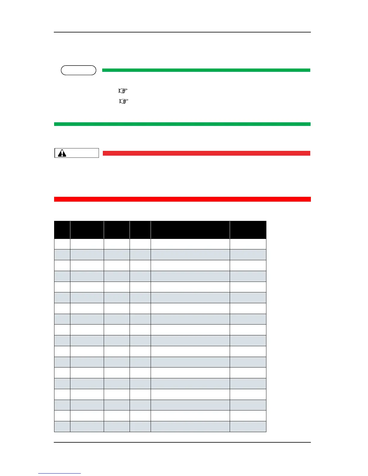
1. Remove the following connectors from the main board assembly.
CAUTION
When connecting or removing the FFC type cables to the main board assembly
connector, always pull or push the cables perpendicularly to the connector.
Pulling or pushing the wire slantwise may damage/short/break the terminals in the
connectors, resulting in a breakdown of the on-board elements.
Table 4-3 Connectors to Main Board Assembly
No. Connector
No.
# of pins Color Connect to Remarks
1 J1 14 White Power board assembly
2 J5 FFC Black Operation panel unit assembly
3 J9 FFC Black CR board assembly J203
4 J10 FFC Black CR board assembly J202
5 J11 FFC Black CR board assembly J201
6 J12 4 White PF ENC assembly
7 J14 8 Black Ink sensor K assembly
8 J15 8 Blue Ink sensor C assembly
9 J16 8 Red Ink sensor M assembly
10 J17 8 Yellow Ink sensor Y assembly
11 J20 2 White PF motor assembly
12 J21 3 White CR motor assembly
13 J22 4 White Pump motor assembly
14 J24 3 White CR_ORG sensor
15 J25 2 White Suction fan 1 assembly
16 J26 2 Black Suction fan 2 assembly
17 J27 3 Black Wiper origin sensor
18 J30 3 Blue Lever sensor assembly
 Loading...