11
3 Wiring
This chapter describes the procedure used to connect DS2 Series products to peripheral
devices and gives typical examples of main circuit wiring as well as I/O signal
connections.
3-1.Main Circuit Wiring
This section shows typical examples of main circuit wiring for DS2 Series servo products,
functions of main circuit terminals, and the power ON sequence.
Observe the following precautions when wiring.
Caution
1. Do not bundle or run power and signal lines together in the same duct. Keep power and signal
lines separated by at least 11.81inch(30cm)
2. Use twisted pair wires or multi-core shielded-pair wires for signal and encoder (PG) feedback
lines.
The maximum length is 118.11inch(3m) for reference input lines and is 787.40inch(20m) for
encoder(PG) feedback lines.
3. Do not touch the power terminals for 5 minutes after turning power OFF because high voltage
may still remain in the servo amplifier.
Please make sure to check the wiring after the CHARGE light is going off.
4. Avoid frequently turning power ON and OFF. Do not turn power ON or OFF more than once per
minute.
Since the servo amplifier has a capacitor in the power supply, a high charging current flows for
0.2s when power is turned ON. Frequently turning power ON and OFF causes main power
devices like capacitors and fuses to deteriorate, resulting in unexpected problems.
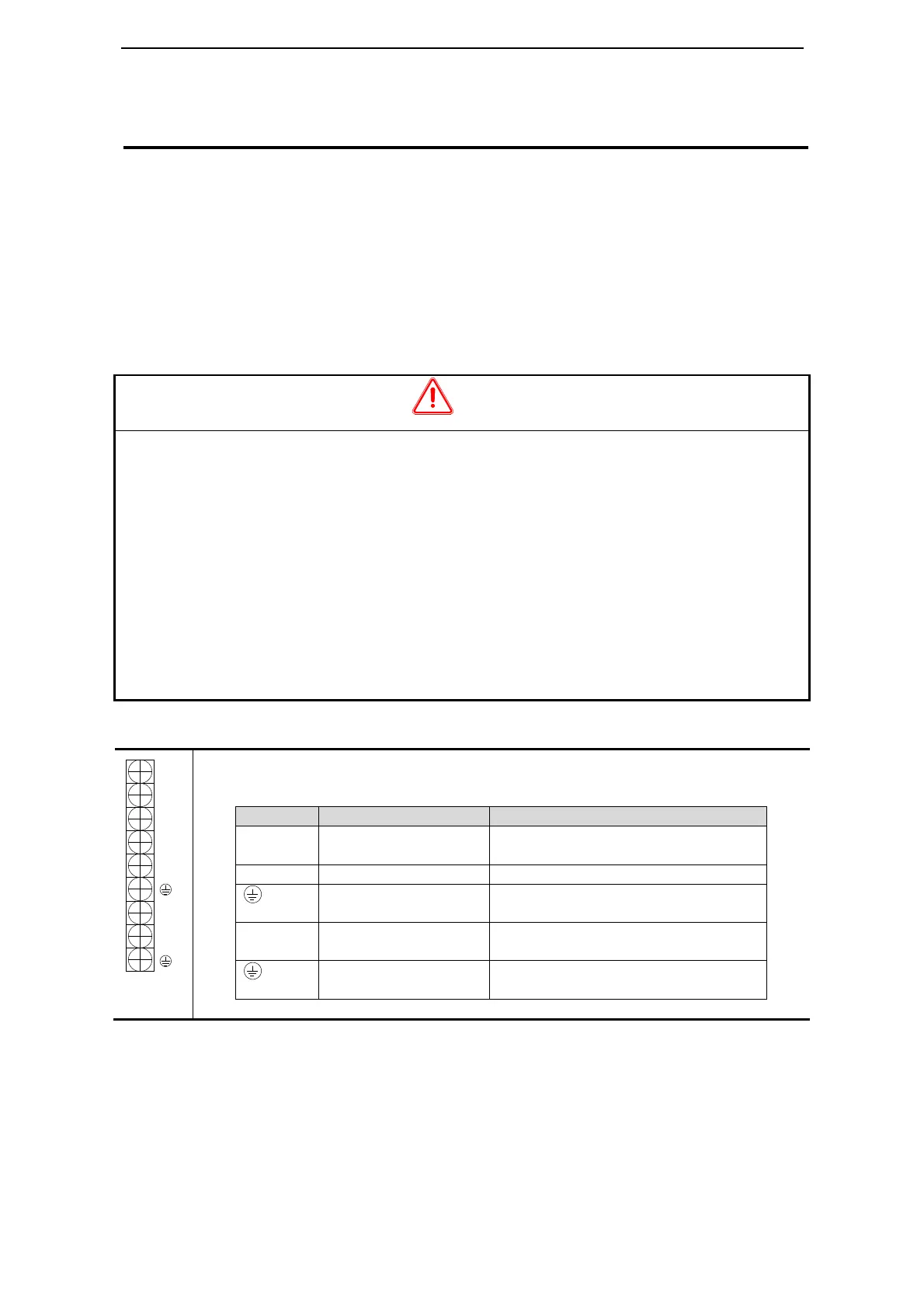
3-1-1.Names and Descriptions of Main Circuit Terminal
resistor connection
Connect regenerative braking resistor
between P+ and PB
Connect to the ground terminal of
motor, to be grounded
circuit
Single-phase AC 200~240V,50/60Hz
Connect to the ground terminal of
power, to be grounded
PB
P+
W
V
U
N
L

 Loading...


