28
internal set speed selection
proportion action command
LED4_5 /G-SEL switch the gain LED5_5
forward side
LED4_6 /CLR clear the pulse LED5_6
reverse side
internal set speed selection
Output signals status
LED1_1 /ALM alarm output LED2_1
checking
U-22 displays I/O terminals status
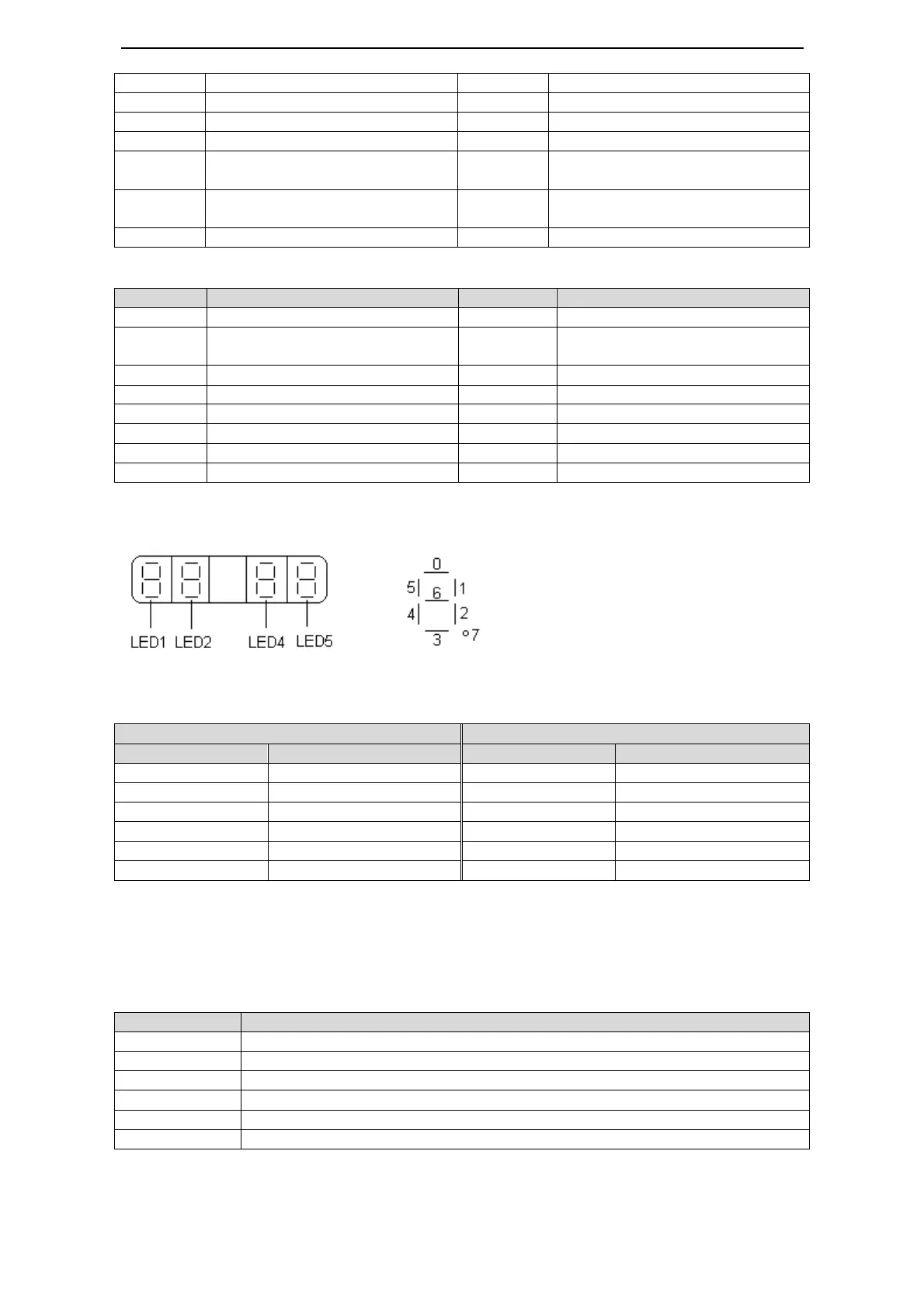
The following diagram describes the input and output terminals status:
Diagram 1 Diagram 2
In diagram 1, LED5 stands for input signals status, and LED2 stands for output signals
status. In diagram 2 there shows the segment No. of each LED.
4-4.Auxiliary Function
Use the operate panel to do application in auxiliary function mode.
, display the system code and data
, display the auxiliary run command and result
Reset parameters to default

 Loading...


