
Do you have a question about the Xinje DS2 series and is the answer not in the manual?
| Control Mode | Position, Speed, Torque |
|---|---|
| Installation Altitude | Below 1000m |
| Category | Servo Drive |
| Output Power | 0.1kW to 7.5kW |
| Communication Interface | RS485, CANopen |
| Encoder Feedback | 17-bit absolute encoder |
| Protection Features | Overvoltage, Undervoltage, Overcurrent, Overload, Overtemperature, Encoder fault |
| Ambient Temperature | 0°C to 55°C |
| Storage Temperature | -20°C to +65°C |
| Vibration Resistance | 5.9 m/s² |
| Shock Resistance | 19.6 m/s² |
| Cooling Method | Natural cooling or forced air cooling |
| Series | DS2 series |
Explains CAUTION and WARNING symbols for hazard levels.
Guidance for checking products upon delivery before installation.
Essential safety steps for installing and wiring the unit.
Critical safety measures to follow during product operation.
Outlines the manual's chapters and content.
Defines the intended users of this manual.
Information on how to obtain the manual.
A checklist to verify received products against orders.
Information on servomotor external appearance and nameplate.
Information on servo driver external appearance and nameplate.
Matches specific servo drives with compatible motors.
Identifies and labels key parts of the products.
Diagram showing the main parts of a servomotor.
Diagrams illustrating the components of various servo driver models.
Procedures and precautions for installing servomotors.
Recommended temperature range for storing servomotors.
Specifies suitable conditions for installing servomotors.
Guidelines for ensuring shaft alignment during installation.
Notes on permissible installation orientation for servomotors.
Precautions against oil and water during installation.
Instructions for managing cables to prevent stress.
Procedures and precautions for installing servo drivers.
Recommended temperature and humidity for storing servo drivers.
Environmental and location considerations for driver installation.
Correct mounting orientation for servo drivers for optimal cooling.
Steps for installing multiple servo drivers side-by-side.
Specifies optimal environmental parameters for control panel installation.
Illustrates main circuit wiring and highlights key precautions.
Details and explains the function of main circuit terminals.
A visual representation of a standard wiring setup.
Lists and maps winding terminals on servo motors.
Introduces the I/O signals used by the servo drivers.
Diagrammatic representation of CN0 and CN1 connector pinouts.
Detailed description of signals for CN0 and CN1 connectors.
Explains the purpose and naming of various I/O signals.
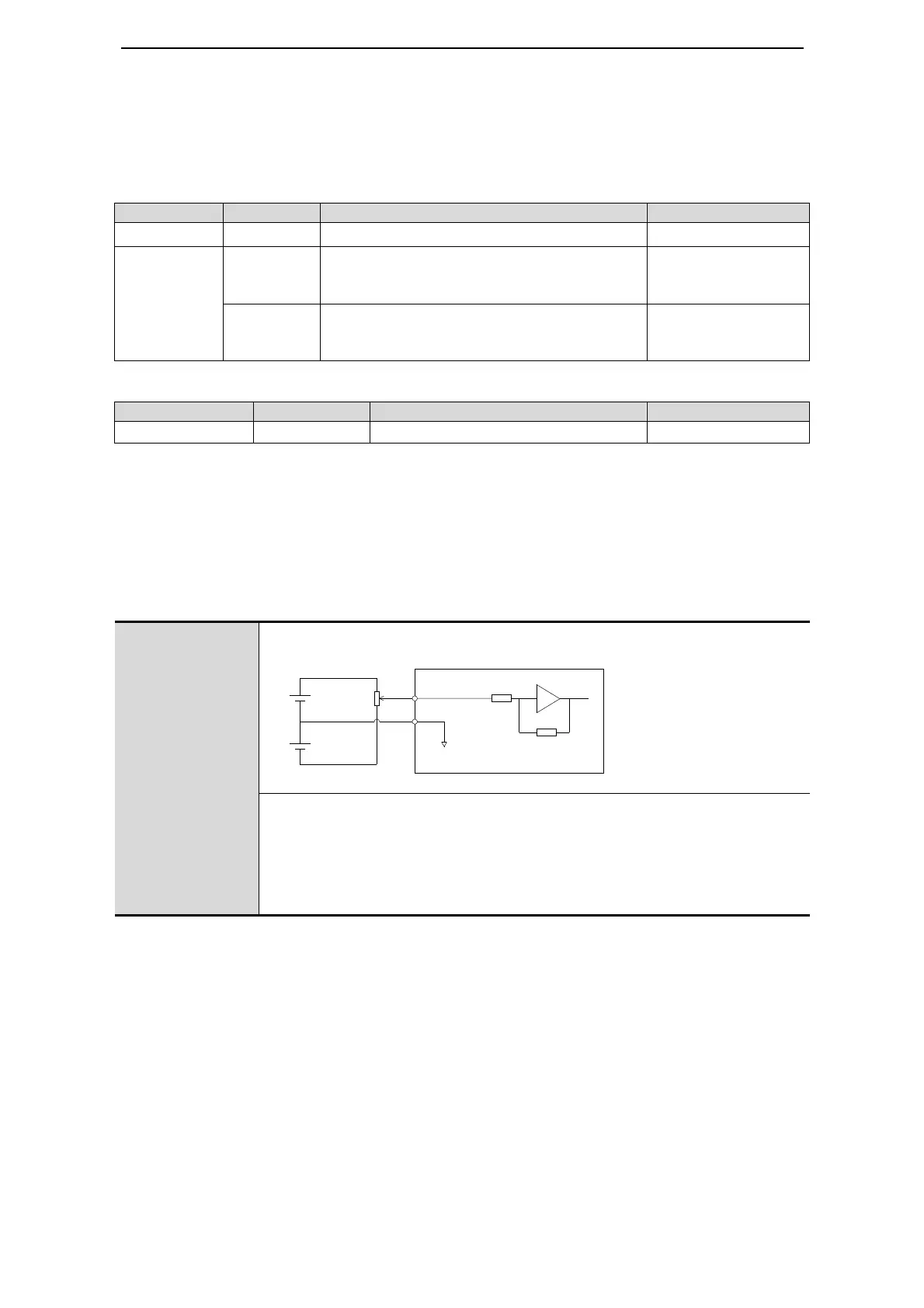
Illustrates common interface circuit configurations for I/O signals.
Guidance on connecting servo encoders.
Describes different ways to connect encoders.
Detailed layout and description of the CN2 connector.
Provides typical wiring examples for various applications.
Example wiring diagram for position control mode operation.
Information on setting up communication ports.
Details for configuring the COM1 serial port.
Details for configuring the COM2 serial port.
Explanation of the purpose and connection of regenerative resistors.
Overview of the operate panel's capabilities.
Describes the purpose of each button on the operate panel.
How to navigate between different operating modes.
Explanation of how to interpret the running status mode displays.
Guide on how to use the monitoring mode to check system status.
Step-by-step instructions for using the monitor mode.
Explains the display for I/O signal status.
Explains the display for I/O terminal status.
How to access and use the auxiliary function mode.
Procedure for checking system information.
Details on using auxiliary run modes like Jog and Trial Operation.
Steps to perform current offset auto-adjustment.
Steps to perform speed command offset auto-adjustment.
Steps to perform torque command offset auto-adjustment.
Function to enable or disable forced servo operation.
Procedure for changing the selected motor type.
How to check and retrieve alarm history.
Steps for restoring factory default parameter settings.
Instructions for enabling external monitoring via PC.
General guidance on how to adjust operational parameters.
Information on alarm codes and how to reset alarms.
Overview of available servo control modes.
Configuration of fundamental servo functions.
Setting the /S-ON signal for servo enable.
How to reverse the motor's rotation direction.
Configuring overtravel limit switches for safety.
Defining motor stop behavior when servo is OFF.
Information regarding the use of the power-off brake.
Parameters for controlling position via external pulse commands.
Selecting the control mode for external pulse operation.
Explanation of different pulse command input formats.
Choosing between CW/CCW and Pulse+Direction modes.
Detailed diagrams and specifications for command pulse signals.
How to set up the electronic gear ratio for position control.
Table listing parameters for electronic gear ratio setup.
Step-by-step guide for calculating and setting the electronic gear ratio.
How to configure filters for position command signals.
Explanation of the pulse error clearing mechanism.
Describes the signal indicating successful positioning.
Explains the signal indicating proximity to the target position.
How to temporarily stop command pulse counting.
Parameters and operations for internal position control.
Selecting the control mode for internal positioning.
Configuring the internal position setpoint.
Explanation of the wait mode for positioning completion.
Explanation of how to change steps based on signals.
Differentiates between relative and absolute positioning.
Setting position parameters for multiple segments.
Details on using the step change signal.
Explanation of the pause current signal function.
Explanation of the skip current signal.
Procedures for finding and setting the reference origin.
Visual guide for finding the reference origin.
Method for defining origin using a signal.
Selecting the control mode for analog voltage speed input.
Configuring the analog value corresponding to rated speed.
Steps for auto-adjusting speed command offset.
Explanation of the /P-CON signal for control mode selection.
How to use the zero clamp function for stopping and holding.
Description of the speed coincidence signal.
Configuration options for limiting motor torque.
Setting the maximum internal torque output.
Setting external torque limits using input signals.
Setting external torque limits via analog voltage.
Using both input signals and analog voltage for torque limits.
Signal indicating when torque reaches its limit.
How to configure soft start for smooth acceleration/deceleration.
Parameters for filtering speed command and feedback signals.
Setting a dead voltage range for speed command input.
Selecting the control mode for internal speed operation.
Configuring three internal speed values.
Using input signals to switch between internal speeds.
How input signals affect speed selection.
A graphical example of speed switching.
Selecting the control mode for pulse frequency speed.
Details on using pulse frequency as a speed command.
Setting the pulse frequency corresponding to rated speed.
Setting a filter for speed command pulses.
Selecting the control mode for analog torque command.
Configuring the analog value corresponding to rated torque.
Steps for auto-adjusting torque command offset.
Setting a filter for torque command signals.
Configuration options for limiting motor torque.
Setting internal speed limits during torque control.
Setting external speed limits during torque control.
Signal indicating when speed reaches its limit.
Setting a dead voltage range for torque command input.
Selecting the control mode for internal torque control.
Setting the internal torque command value.
How to switch control modes using an external signal.
Details on alarm and alarm reset signals.
Details on the warning signal.
Details on the rotation checking signal.
Details on the servo ready signal.
Details on the encoder Z phase output signal.
Details on the AB phase feedback signal for encoders.
How input and output signals are distributed to terminals.
Explains how input signals are assigned to terminals.
Default assignments for input terminals.
Explains how output signals are assigned to terminals.
Default assignments for output terminals.
Introduction to adjusting servo gains.
How to configure gains for the speed loop.
How to configure gains for the position loop.
Setting the proportional gain for the position loop.
Setting the feedforward gain for the position loop.
Practical advice for tuning servo parameters.
Explanation of the P-CON signal for P/PI control.
How to switch between different gain sets online.
Detailed specifications for various servo motor models.
Tables listing motor specifications like power, speed, torque.
Graphical representation of motor performance curves.
Visual documentation of motor dimensions.
General specifications for the servo drivers.
Key electrical and environmental data for servo drivers.
Detailed performance metrics for servo drivers.
Visual documentation of servo driver dimensions.
A comprehensive list of alarm codes, their causes, and solutions.
Description of the specific application mode.
Introduction to the hardware setup for the example.
Analysis of the application's needs and operational considerations.
Details of signals and terminals used in the example.
Steps for testing and debugging the application setup.


