49
Detailed explanation:
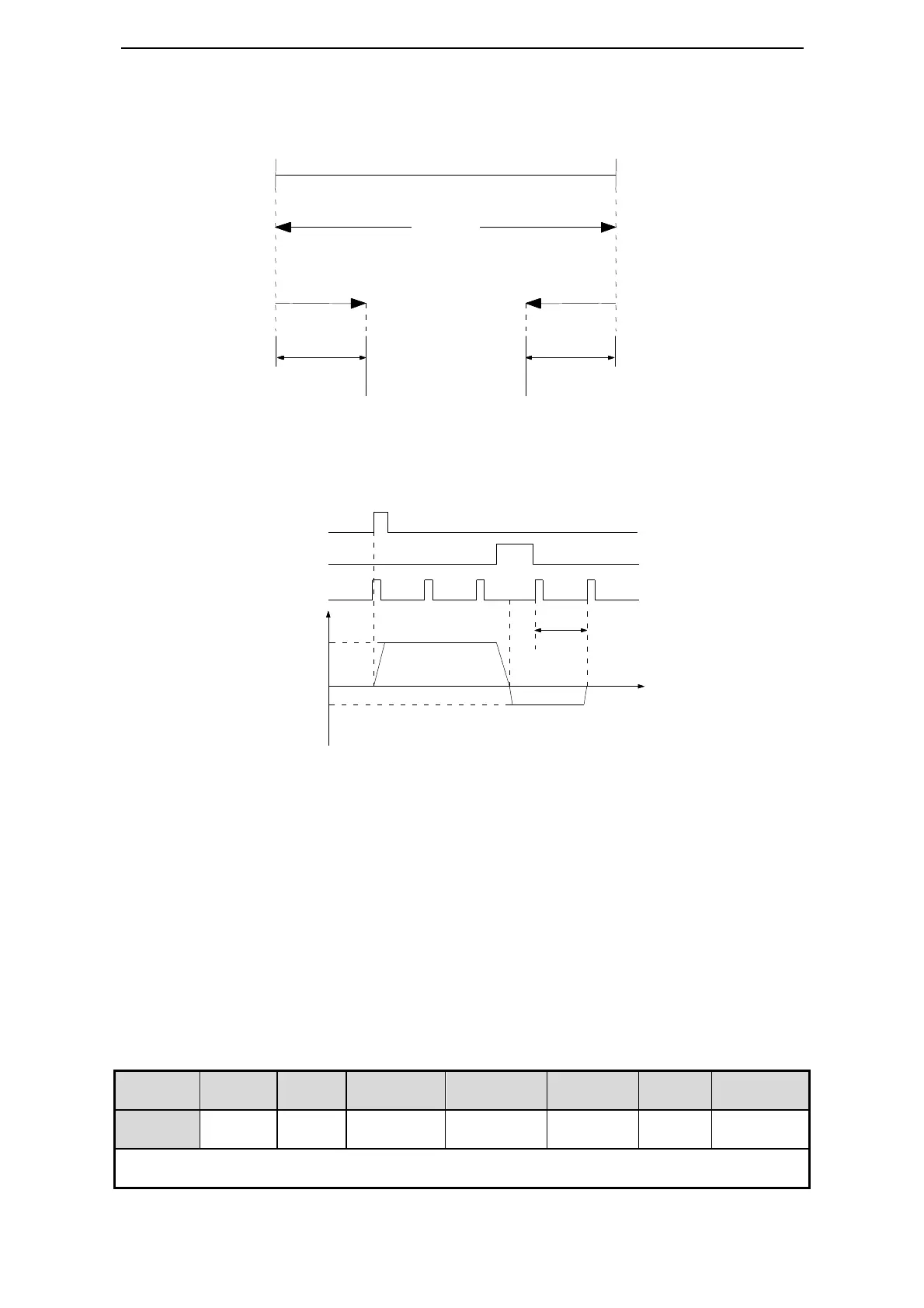
Find reference origin diagram:
The timing diagram of finding reference origin of forward side:
Steps:
1. Install limit switch at forward and reverse side. At the rising edge of /SPD-A, motor
runs forward at the speed of P2-95 to find the reference origin of forward side.
2. After the working table hit the limit switch, the motor stop as the mode set by parameter
P0-06.H.
3. Motor leaves the limit switch at the speed of P2-96. After the working table left the
limit switch, the motor run at the Z phase signal position of No.n optical encoder. This
position is considered as the coordinates origin, n is decided by parameter P2-94.
(2) Define the reference origin
Function:
In external pulse command postion mode (mode 6) and internal position mode (mode 5),
define the current position as the reference origin at the rising edge of /SPD-D.
Signal setting:
/SPD-A
/P-OT
/Z
V
t
①
②
③
P2-96
P2-95
P2-94
mode
distribute
on
stributed to input terminal by P5
2. In internal speed mode (mode 3), /SPD-D auto-switch to the direction select signal of internal speed.
P0-06.H
P0-06.H
of forward side
of reverse side
①
②
③

 Loading...


