65
5-12-3. Output terminal distribution
00: pointless
y: 0 always open
1 always close
x: output terminal
no.
terminal input
signal from S0x
always valid
signal from S0x
If the distributed terminal has other signal, please set the signal to other terminal or set to unused.
Setting range of input terminal for each type:
DS2-20P4
DS2-20P7
n.0000~n.0002
n.0010~n.0012
DS2-2□P□-A
DS2-2□P□-B
n.0000~n.0003
n.0010~n.0013
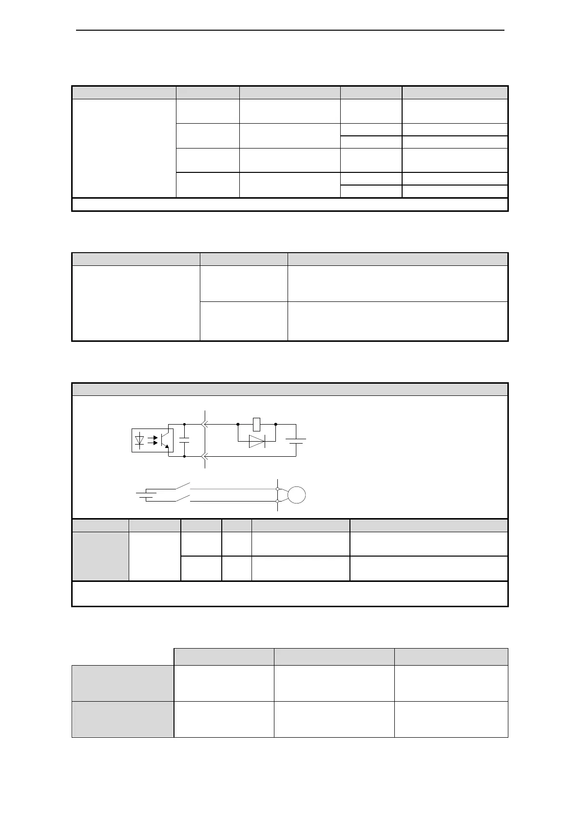
Example: take /BK signal of DS2-21P5-A as an example to explain output terminal
distribution.
Output terminal wiring example
2
1
BK
+24V
BK-RY
+24V
BK-RY
COM
SO3
6
7
Brake power on and loosen, motor
can work
COM
Brake power off and tighten, motor
cannot work
DY) to other terminal or unused
to avoid terminal signal conflict.
5-12-4. Default setting of output terminal
SO1 SO2 SO3
DS2-20P4
DS2-20P7
DS2-2□P□-A
DS2-2□P□-B
S03 output of DS2-21P5-A is at
CN1 (DB15). Pin no. of S03 is
CN1-6, pin no. of COM is
CN1-7.

 Loading...


