18
Incremental encoder servo unit host device
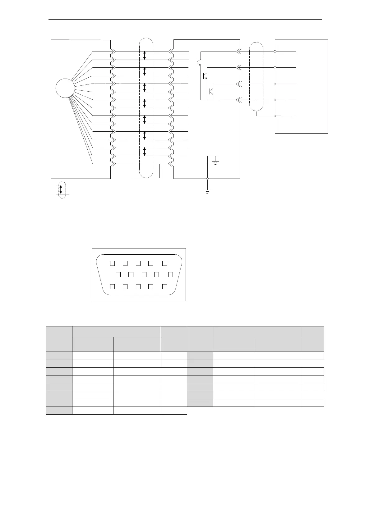
3-3-2.CN2 Encoder Connector Terminal Layout
CN2 Connector Terminal Layout
The following diagrams are the layout of CN2 connector (face the solder pin).
CN2 Connector Terminal Description
Driver
Side
Encoder Side On Motor
Name
Driver
Side
Encoder Side On Motor
Name
series
series
series
series
3-4.Standard connection examples
This chapter explains the standard connection examples as the spec and control type.
The I/O signals used on input and output terminals are assigned by default. This
assignment could be changed in various conditions. Please refer to 5-12.
910
15 14 13 12 11
12345
6
78
CN1
(
DB15
)
8 AO
9 BO
10 ZO
13 GND
X0
X1
X2
COM
0V
CN2
A+
A-
B+
B-
U-
Z-
Z+
+5V
GND
SHIELD
W-
W+
V-
V-
W+
W-
Connector shell
GND
+5V
Z+
Z-
U+
U-
B-
B+
A-
A+
(shell)
Shield calbes
PG
P
P
P
P
P
P
P
P
Means twisted wire shield cables

 Loading...


