5-106
E
POWR
1
2
3
4
5
6
7
8
9
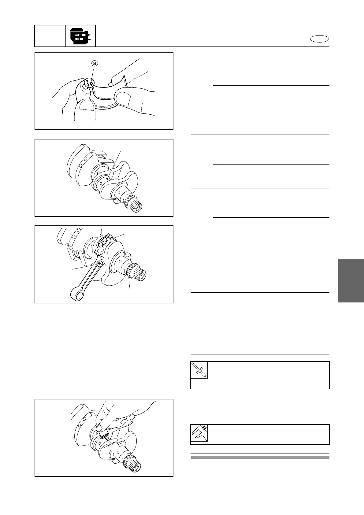
2. Install the upper bearing into the connect-
ing rod and lower bearing into the connect-
ing rod cap.
NOTE:
• Install the connecting rod bearings in their
original positions.
• Insert the projection a of each bearing into
the slots in the connecting rod cap and con-
necting rod.
3. Put a piece of Plastigauge 1 onto the
crankshaft pin, parallel to the crankshaft.
NOTE:
Do not put the Plastigauge over the oil hole in
the crankshaft pin.
4. Install the connecting rod onto the crank-
shaft pin.
NOTE:
• Apply engine oil to the connecting rod bolts
threads and nut seats.
• Make sure that the “Y” mark b on the con-
necting rod faces towards the timing chain
drive gear c of the crankshaft.
• Make sure that the characters d on both the
connecting rod and connecting rod cap are
aligned.
5. Tighten the connecting rod nuts to the
specified torques in 2 stages.
NOTE:
Do not turn the connecting rod until the crank-
shaft pin oil clearance measurement has been
completed.
6. Remove the connecting rod cap and mea-
sure the width e of the compressed Plas-
tigauge on each crankshaft pin.
T
R
.
.
Connecting rod nut:
1st: 51 N·m (5.1 kgf·m, 37.6 ft·lb)
2nd: 90°
Crankshaft pin oil clearance:
0.020–0.056 mm (0.0008–0.0022 in)
1
b
d
c
e
Crankcase, connecting rod, and piston
 Loading...