6-5
E
JET
PUMP
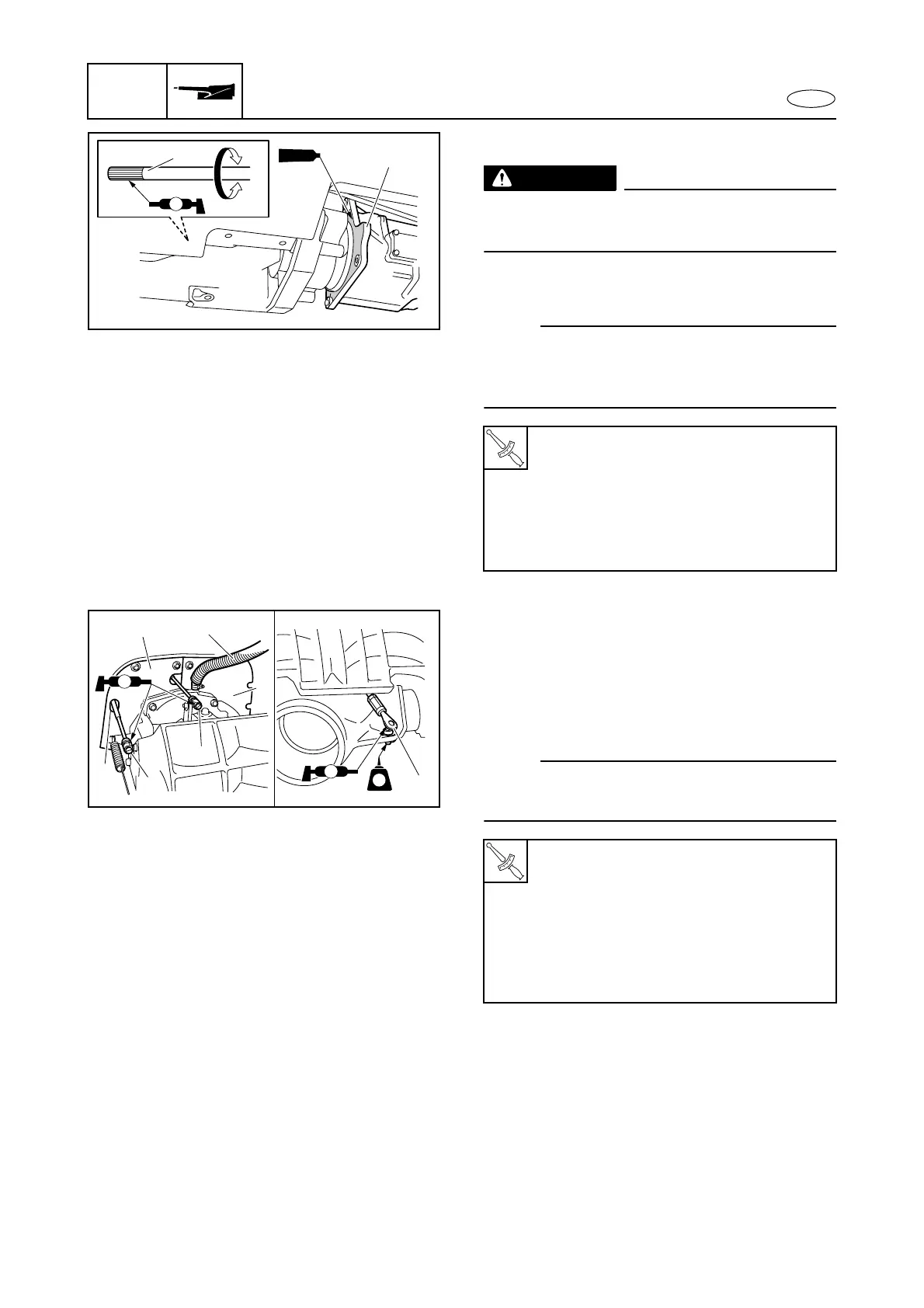
Jet pump unit installation
WARNING
Be sure to remove the battery before in-
stalling the jet pump unit.
1. Install:
• Jet pump unit 1
NOTE:
Rotate the drive shaft 2 to align the splines on
the drive shaft with the splines on the inside of
the intermediate drive shaft.
2. Install:
• Rubber plate 1
• Rubber plate 2
• Spout hose 3
• QSTS rod joint 4
• Shift cable joint 5
• Steering cable joint 6
NOTE:
When installing the rubber plate 1, pass the
shift cable 5 through the hole a in the plate.
3. Check:
• Steering operation
• Shift operation
• QSTS operation
Do not operate correctly → Reinstall.
T
R
.
.
Jet pump unit assembly bolt:
M10
× 45 mm:
40 N·m (4.0 kgf·m, 29.5 ft·lb)
LOCTITE 572
M6
× 30 mm:
8 N·m (0.8 kgf·m, 5.9 ft·lb)
LOCTITE 572
T
R
.
.
Rubber plate bolt:
7 N·m (0.7 kgf·m, 5.2 ft·lb)
LOCTITE 572
Spout hose clamp:
2 N·m (0.2 kgf·m, 1.5 ft·lb)
Steering cable joint:
7 N·m (0.7 kgf·m, 5.2 ft·lb)
LOCTITE 242
M
1
2
1194E
3
5
a
2
6
4
1
AA
AA
LT
242
Jet pump unit
 Loading...