E
ELEC
– +
1
2
3
4
5
7-31
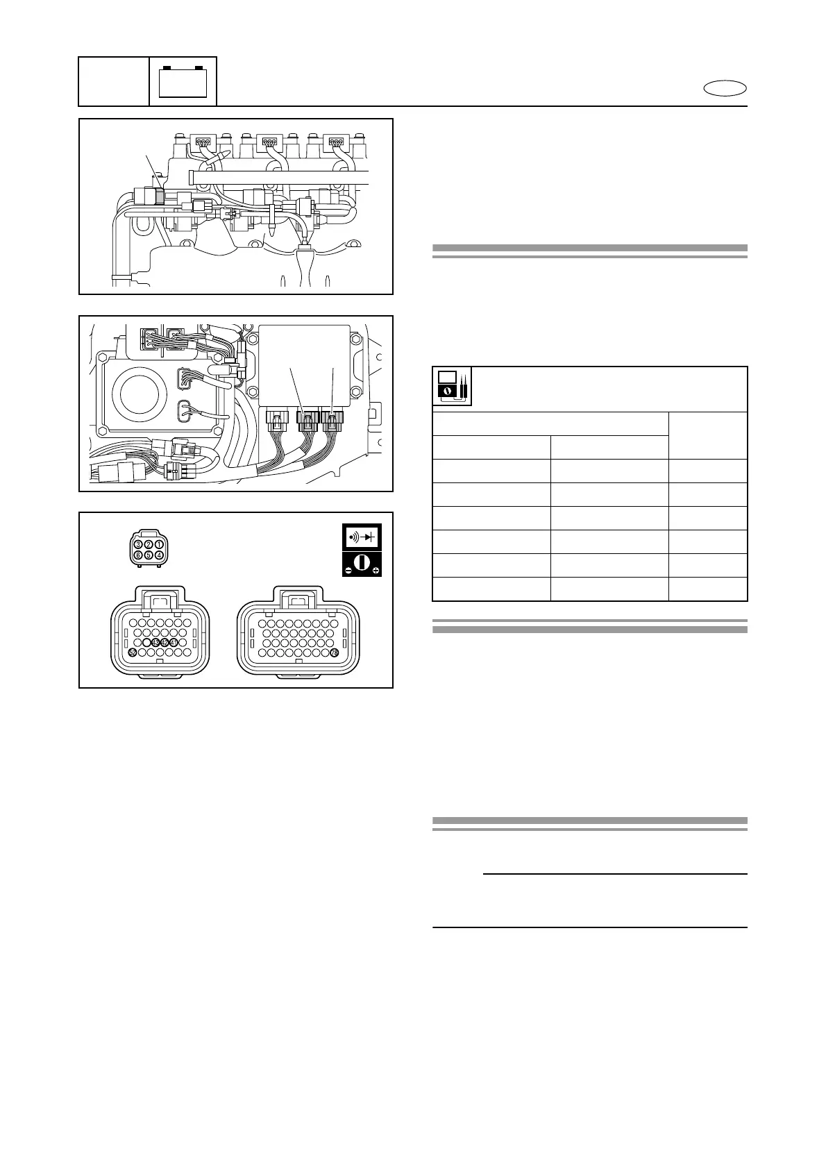
3. Check:
• TPS circuit
No continuity → Replace the wiring har-
ness assembly.
Wiring harness is correct → Replace the
throttle body assembly.
Checking steps:
1. Disconnect the throttle body assembly
coupler 1.
2. Disconnect the ECM couplers 2 and 3.
3. Check the wiring harness for continuity.
Wiring harness continuity:
Terminal No.
Color
Coupler 1 Coupler 2, 3
142P
244O
378G
443P/B
541B/O
652L
1
2 3
1
d
23
Accelerator position sensor
1. Check:
• APS output voltage
Out of specification → Measure the APS
input voltage.
Checking steps:
NOTE:
When checking the APS using the YDIS, do
not start the engine.
Control system
 Loading...