1.2 Configuration with a Direct Drive Servomotor
1-3
1
Peripheral Devices and System Congurations
1.2
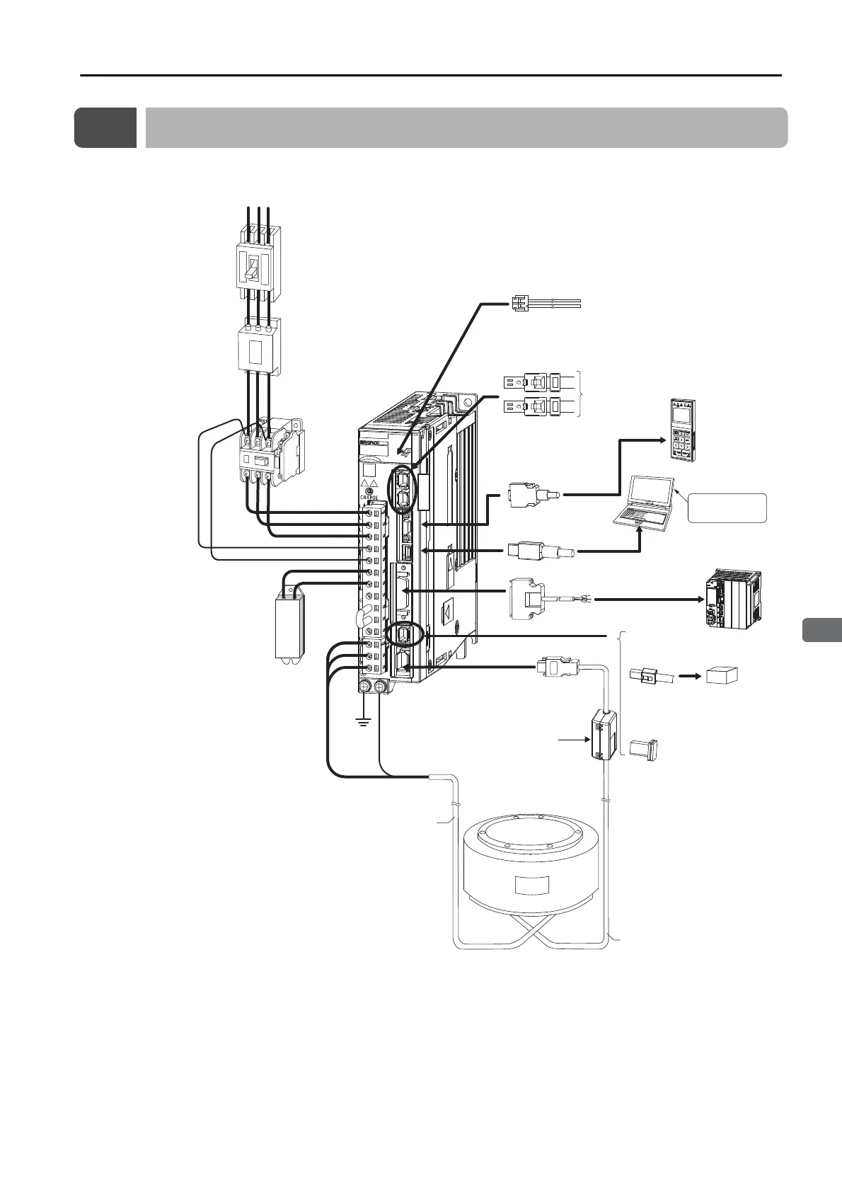
Configuration with a Direct Drive Servomotor
*1. The peripheral devices are described using a MECHATROLINK-III Communications Reference SERVOPACK for
a three-phase 200-VAC power supply input as an example. The shapes of the connectors and pin layout may
be different for SERVOPACKs with other power supply input specifications and for other interfaces.
*2. The connected devices depend on the interface.
For MECHATROLINK-II communications references: Other MECHATROLINK-II stations
For analog voltage/pulse train references: There is no CN6 connector.
External Regenerative
Resistor
Noise Filter
Molded-case
circuit breaker
Magnetic Contactor
I/O Signal Cable
SERVOPACK
*1
Power supply
Three-phase, 200 VAC
*1
R S T
Computer Cable
External
Regenerative
Resistor
Cable
Control Power
Supply Cable
Digital Operator
(JUSP-OP05A-1-E)
Digital Operator
cable
Host controller
MECHATROLINK Communications Cable
*1
To next
MECHATROLINK-III
station
*2
C
N
6
Safety Function Device Cable
Safety function device
SERVOPACK
main circuit wires
Servomotor Main
Circuit Cable
Direct Drive
Servomotor
Encoder Cable
Analog Monitor Cable
Computer
Battery Case (Required when
an absolute encoder is used.)
When not using a safety function,
leave the Safety Jumper Connector
connected to the SERVOPACK.
Ground
cable
Engineering
Tool
(page 12-3)
(page 12-25)
(page 12-6)
(page 8-7)
(page 12-10)
(pages 10-30 and 10-31)
(page 10-11)
(page 10-10)
(page 8-18)
(page 10-29)
(page 12-32)
(pages 10-12 and 10-
12)
(page 10-13)
(pages 10-14, 10-17 and 10-20)
(page 14-4)
Surge Absorbers (page 12-31)
Reactors (page 12-28)
(page 13-2)
 Loading...


