4 Cabling the AC 800F
4-56
4.2.13 Cabling AC 800F for operation in redundancy mode
Two AC 800F can be linked to enable operation in redundancy mode. In addition to
the Ethernet module in slot E1 for normal network communication a second Ethernet
module is present in slot E2. A point-to-point connection called the ‘redundancy link’ is
set up between the Ethernet modules in the E2 slots of the two AC 800F.
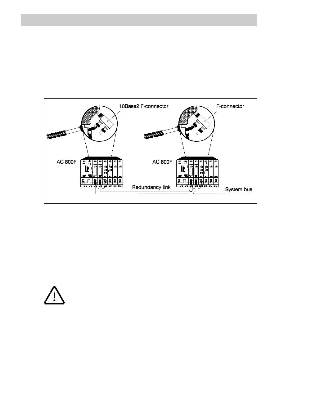
Fig. 4-33 shows two AC 800F with a redundancy link via the 10Base2 modules.
Fig. 4-33 Cabling AC 800F for operation in redundancy mode
Connect the redundant network cable. Proceed as described for the system bus.
Make sure that there is no connection between the redundancy link
and another network.

 Loading...


