7 Functional Description of the Fieldbus Modules
7-11
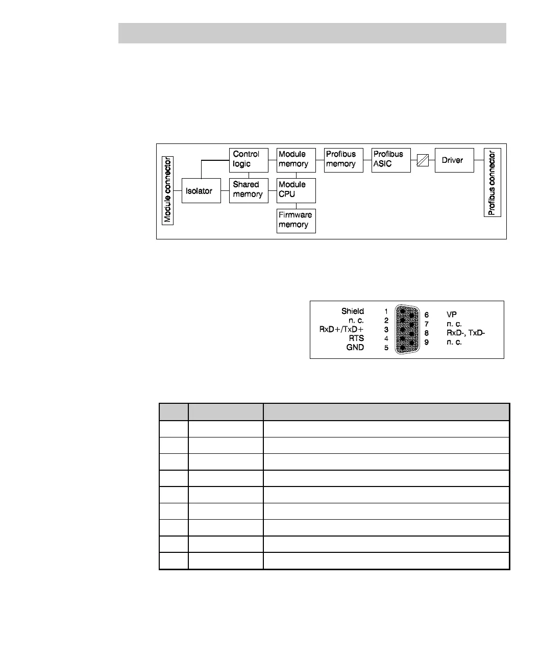
FI 830F block diagram
The DP Profibus is electrically isolated from the system in accordance with the
standard. The communication and control signals are isolated via high-speed
optocouplers. The power for the channels is provided by an electrically isolated
DC/DC converter.
Fig. 7-3 FI 830F block diagram
Connector pin assignment
The assignment of the 9-pin
communication connector complies
with DIN 19245/EN 50170. Ready-
made cables from any supplier can
be connected.
Fig. 7-4 FI 830F connector pin assignment
Pin: Signal Description
1 shield Shield
2 n. c. Not used
3 RxD+/TxD+ Transmit/receive data - PLUS
4 RTS Repeater control signal (direction control)
5 GND Data transmission potential (ground to 5 V)
6 VP 5 V supply voltage of terminating resistors
7 n. c. Not used
8 RxD-/TxD- Transmit/receive data - MINUS
9 n. c. Not used

 Loading...


