8 Accessories
8-2
8.1.2 Installing the battery module
When plugging a module into the AC 800F for the first time, note that there may be
electrostatic discharge from the module which may cause malfunctions of the
AC 800F electronics.
To avoid damage resulting from electrostatic discharge (ESD), proceed as de-
scribed below when installing or replacing a module. Note that this procedure is
mandatory:
1. Remove the cap (dummy panel) from the appropriate slot.
• Do not remove an Ethernet module while the AC 800F is run-
ning, i.e. under power!
• Note that the electromagnetic compatibility will be impaired
when the housing is opened. Removing a dummy panel may re-
duce the EMI suppression and the EMI/RFI shielding capabilities of
the AC 800F.
2. Establish a good electrical contact between a passive part of the housing and the
special ESD protection bag in which the module has been delivered to you.
3. Take the battery module out of the special ESD protection bag. Do not touch the
board. Only touch the module front panel.
4. Carefully insert the battery module into the appropriate slot E1 or E2. Touch the
AC 800F housing with your free hand, either while inserting the module into the
slot or at least directly prior to inserting it in order to provide for discharge.
There are contacts on the upper and lower edge of the battery module which act
as high-resistance bridges towards the housing. This eliminates residual charges
that may still exist and avoids electromagnetic interference.
5. Hand-tighten the screws on the module front panel top and bottom. Only then it
can be guaranteed that the specified EMC limit values are met.
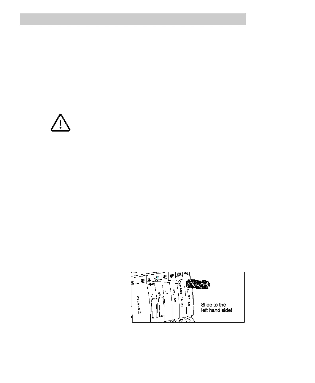
6. Lock the slide-lock to cover
the upper locking screw. Use
an appropriate tool to slide the
lock to the left hand side until
the screw head is completely
covered and the Lock inscrip-
tion is visible.
Fig. 8-1 Locking the module slide lock
Only if the module has been plugged in and locked properly, it will be switched on
and identified.

 Loading...


