7 Functional Description of the Fieldbus Modules
7-29
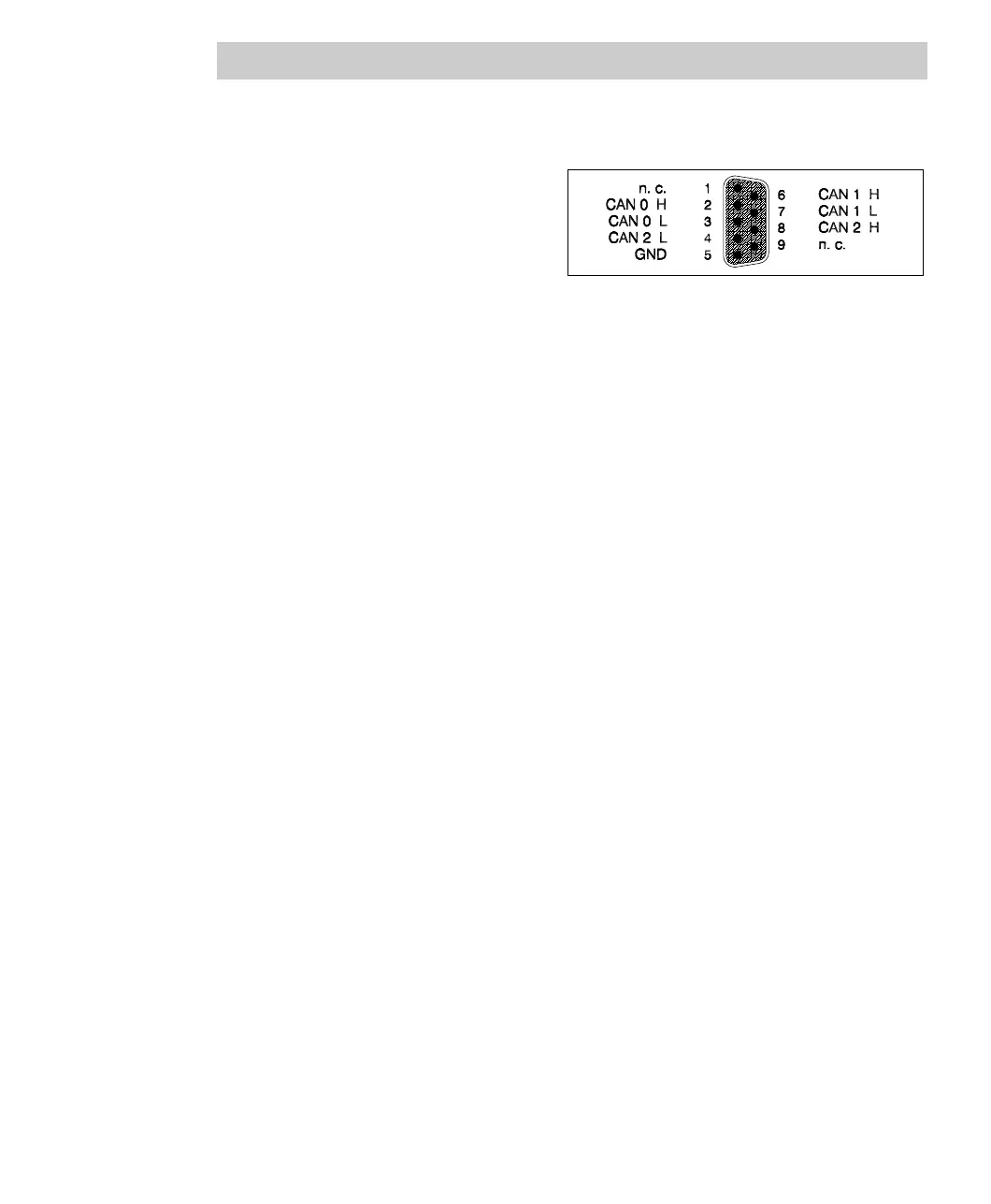
Connector pin assignment
The pin assignment of the
communication connector (9-pin
Sub-D socket) is identical with the
CAN connection of the link
modules in the Freelance 2000
system.
Fig. 7-13 FI 810F connector pin assignment
Electrical isolation
The three CAN channels are electrically isolated from each other and from the
system. To achieve this, the communication signals are isolated through high-speed
optocouplers. The power for the channels is provided by an electrically isolated
DC/DC converter with three isolated output voltages.
7.4.3 Technical data
Features
• Three CAN channels, el. isolated from each other and from the system
• CAN drivers for differential bus structure
• Serial 4 KBit EEPROM with 10
7-
write cycles for system parameters
General features
Rated voltage 5 V ± 3%, from the CPU board
Power consumption 1.6 W ... 2.6 W, depending on communication
Channel supply
Ratedvoltage 5V±10%
Power consumption. max. 0.15 W, when idling
(per channel) max. 0.35 W, when communicating
max. 0.5 W, with CAN bus shorted
Weight 145 g
Plugging/removal during operation Permissible, if slide lock is set properly, see
Section 7.1.

 Loading...


