7 Functional Description of the Fieldbus Modules
7-14
7.2.3.1 Transmission technology
Data transfer from the fieldbus module to the fieldbus devices is possible in two ways,
conforming to the standards:
• RS485 transmission
• Transmission via fiber-optic cables (FO cables) with the appropriate converters
from another supplier, for RS485 ➩ FO cable and FO cable ➩ RS485 transition.
Both transmission techniques provide for reliable long distance transmission with a
high transmission rate, and simple electromechanical parts. A shielded TP (twisted-
pair) copper cable is the hardware required for RS485 transmission. It connects all
devices to the bus structure (line).The bus structure allows for non-reactive coupling
and decoupling of stations or stepwise commissioning of a system. Later extensions
have no impact on stations that are already working on the bus.
Up to 32 nodes (masters and slaves) can be grouped in a single segment. When
using more than 32 nodes, several segments linked to each other through repeaters
(power amplifiers) are needed. A maximum of 127 nodes can be connected to a
Profibus DP line in this way. The max. line length depends on the transmission rate.
The specified length can be increased when using repeaters. Note that it is
recommended to use not more than three series-connected repeaters on a line.
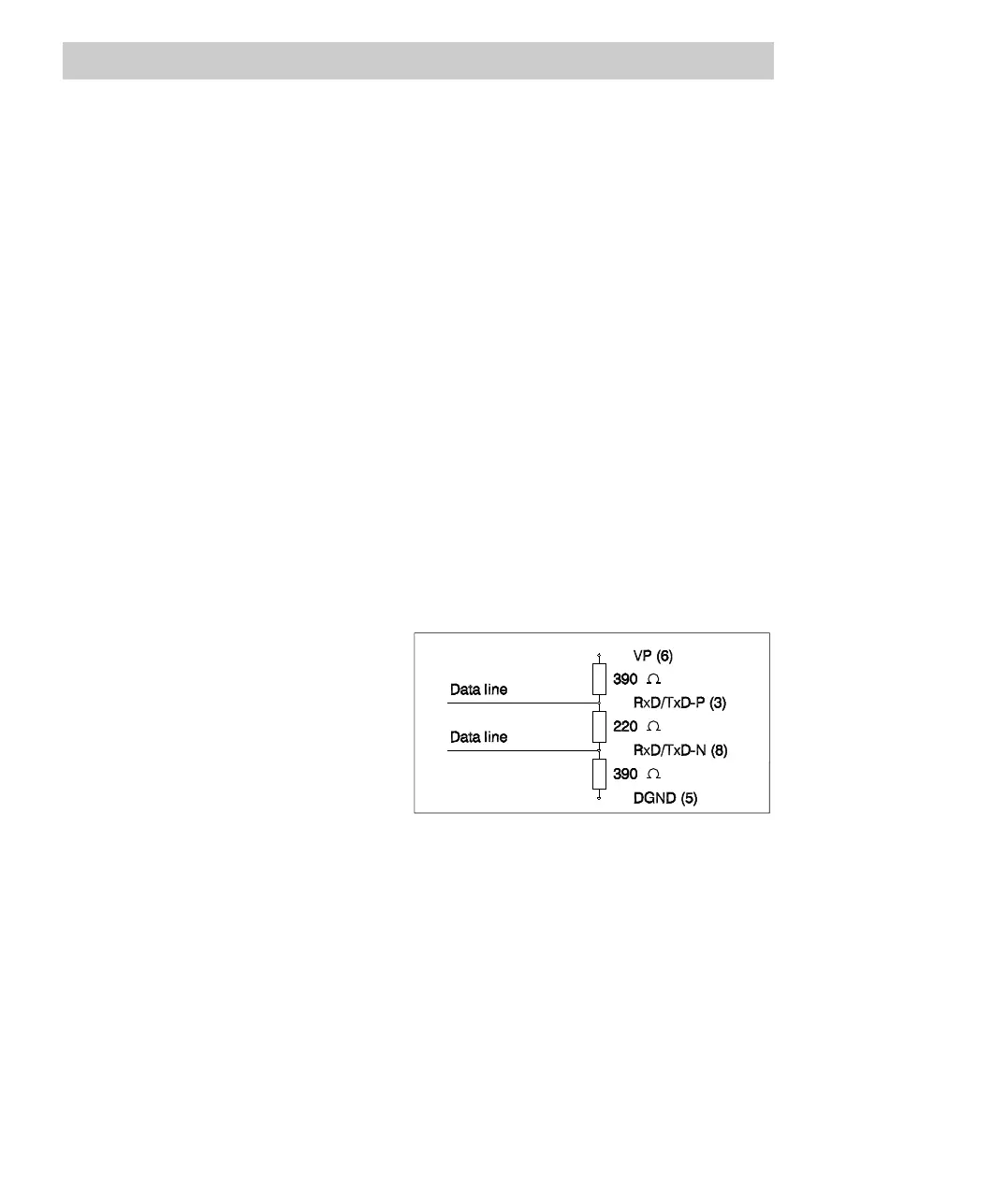
Every bus segment is terminated
at each end through an active
bus termination.
If the Profibus module is located
at the end of a line, make sure
that the bus termination, which
may be connected into the line,
is available in the Profibus
connector.
Fig. 7-5 FI 830F bus termination
To ensure trouble-free operation, make sure that the two bus terminations are always
under power.

 Loading...


