4 Cabling the AC 800F
4-6
When installing power supply module SD 802F, observe the following rules:
• The power supply module has no mains switch, provide one for each supply
(standard and redundant).
• It is recommended to usea4ATfusetoIEC/EN60127-2/V, ceramic cartridge
5 x 20 mm, high breaking capacity, melt index of at least 22 A
2
s e.g. Wickmann,
type 181.
Do not use fuses with a smaller melt index.
• Power cable: copper, min. length 1 m, cross-sectional area 0.75 mm
2
• Provide a functional grounding as described in Section 3.2.
• Rated voltage: 24 V DC.
Permissible input voltage range: 19.2 ... 32.5 V DC
• Connection to a three-phase mains via a three-phase bridge rectifier is
permissible. However, a protective separation is mandatory.
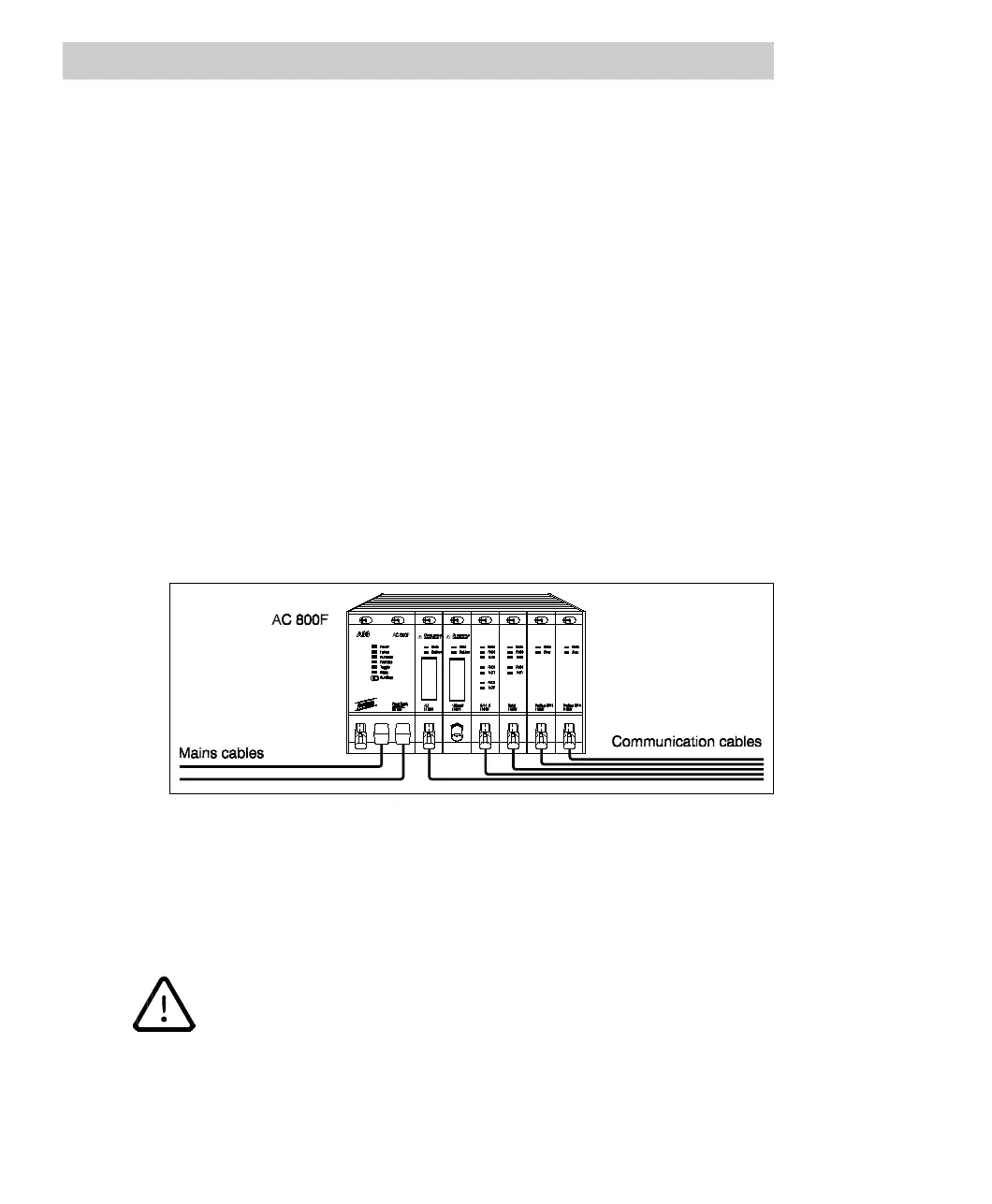
• Lay the mains cable(s) separately (not too close to communication cables), as
seen in the following illustration.
Fig. 4-6 Laying cables of power supply module SD 802F
• Power supply module SD 802F has two 24 V DC inputs and outputs a 3.3 V and
5 V voltage. It suppresses mains noise, acts as a buffer for up to 20 ms with a
minimum input voltage in case of a power failure, and generates a power-fail
signal.
When using the power supply module SD 802F together with the CPU
board PM 803F, a maximum of 3 Profibus modules FI 830F can be
supported.
Use the power supply module SD 812F with software version 7.1 and
higher for running a maximum of 4 Profibus modules FI 830F.

 Loading...


