7 Functional Description of the Fieldbus Modules
7-32
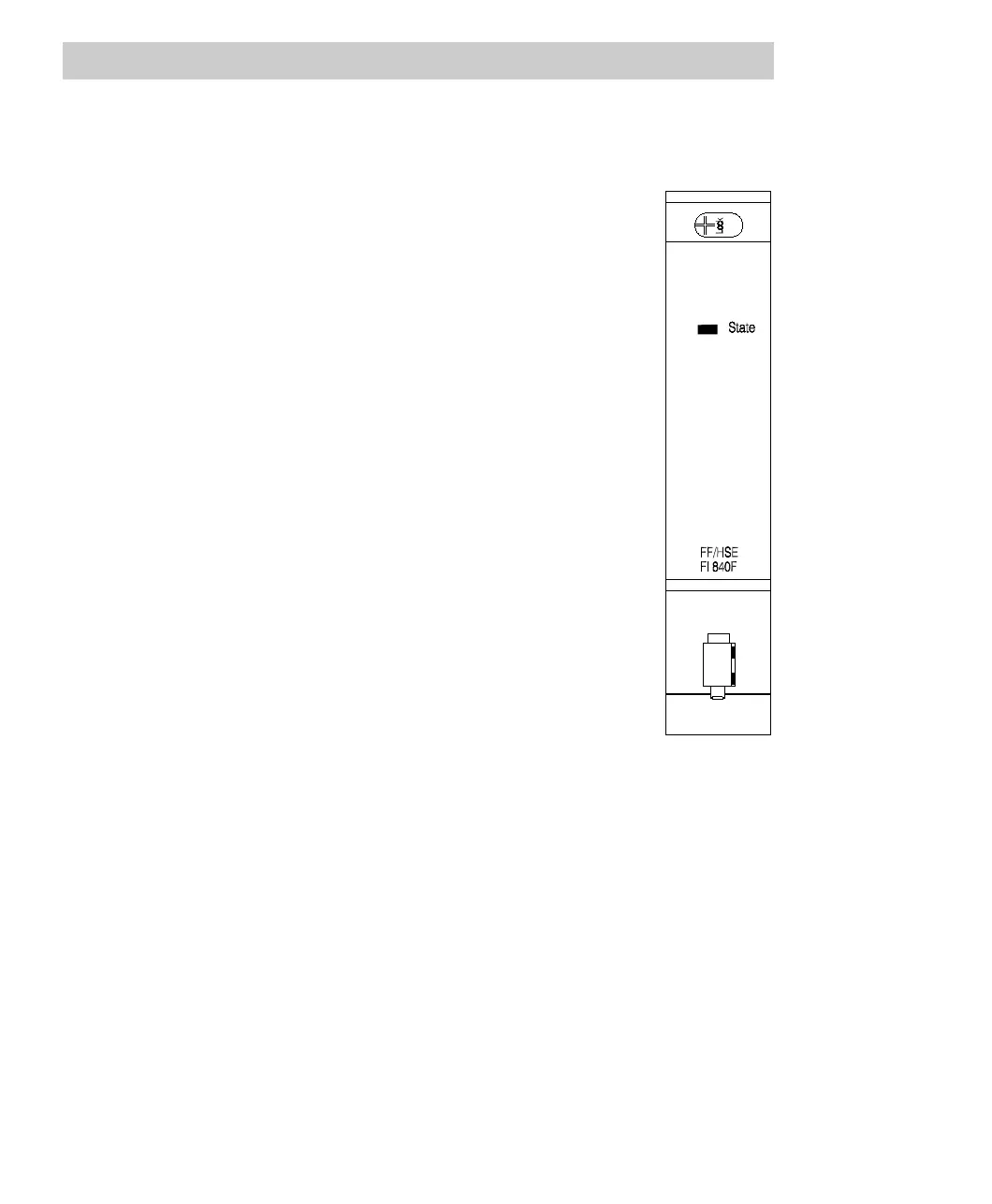
Description of the status indicators
The module FI 840F has a multicolor LED which indicates the
current module state:
State LED
• Off No voltage applied, module is separated.
• Green Power supply switched on, module identified
and ready to operate according to
configuration.
• Orange Power supply switched on, module identified:
-intermediate state after normal module startup
or
-configuration mode of Boot Loader (see
Section 5.4)
• Orange flashing Power supply switched on, module identified;
module not connected to a proper bus
structure.
• Red Power supply switched on:
-module not yet identified (short time, during
module startup) or
-error occurred during module test
Two single-color LEDs are provided on the RJ45 connector, indicating the current
communication state. Although these LEDs are not labeled, they can be clearly
identified through their color. The lower, green LED indicates the link state, the upper,
yellow LED indicates the transmission rate.
FF/HSE Link LED
• Off No active link, neither 10 Mbit/s nor 100 Mbit/s.
Communication is not possible.
• Green static Active link. Communication is possible, but there is currently
no data traffic.
• Green flashing Active link. Communication is possible.
FF/HSE Speed LED
• Off The module has recognized a 10 Mbit/s data link.
• Yellow static The module has recognized a 100 Mbit/s data link.

 Loading...


