4 Repair
4.7.5. Removal of motor, axes 4, 5 and 6
3HAC022032-001 Revision: E204
© Copyright 2004-2008 ABB. All rights reserved.
4.7.5. Removal of motor, axes 4, 5 and 6
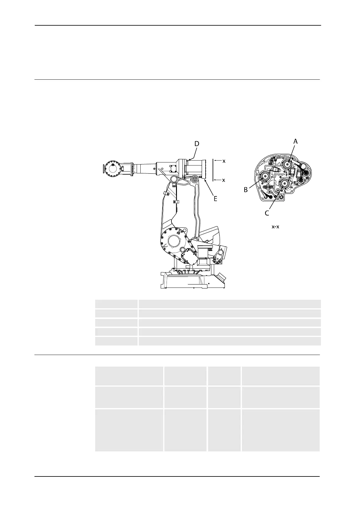
Location of motors
The motors, axes 4, 5 and 6, are located as shown in the figure below. (The figure shows the
IRB 4400.)
The motor and the drive gear of each axis constitute one unit.
A more detailed view of the component and its position may be found in chapter Foldouts in
the Product manual, reference information.
xx0300000164
Required equipment
A Motor unit, axis 4
B Motor unit, axis 5
C Motor unit, axis 6
D Attachment screws and washers, motor
E Connection box
Equipment, etc.
Spare part
no.
Art. no. Note
Standard toolkit 3HAC
17594-1
The contents are defined in
section Standard toolkit on
page 264.
Other tools and
procedures may be
required. See references
to these procedures in the
step-by-step instructions
below.
These procedures include
references to the tools
required.
Continues on next page

 Loading...


