2 Installation and commissioning
2.4.4. Electrically restricting the working range of axis 3
73 3HAC022032-001 Revision: E
© Copyright 2004-2008 ABB. All rights reserved.
2.4.4. Electrically restricting the working range of axis 3
Electrically restricting the working range
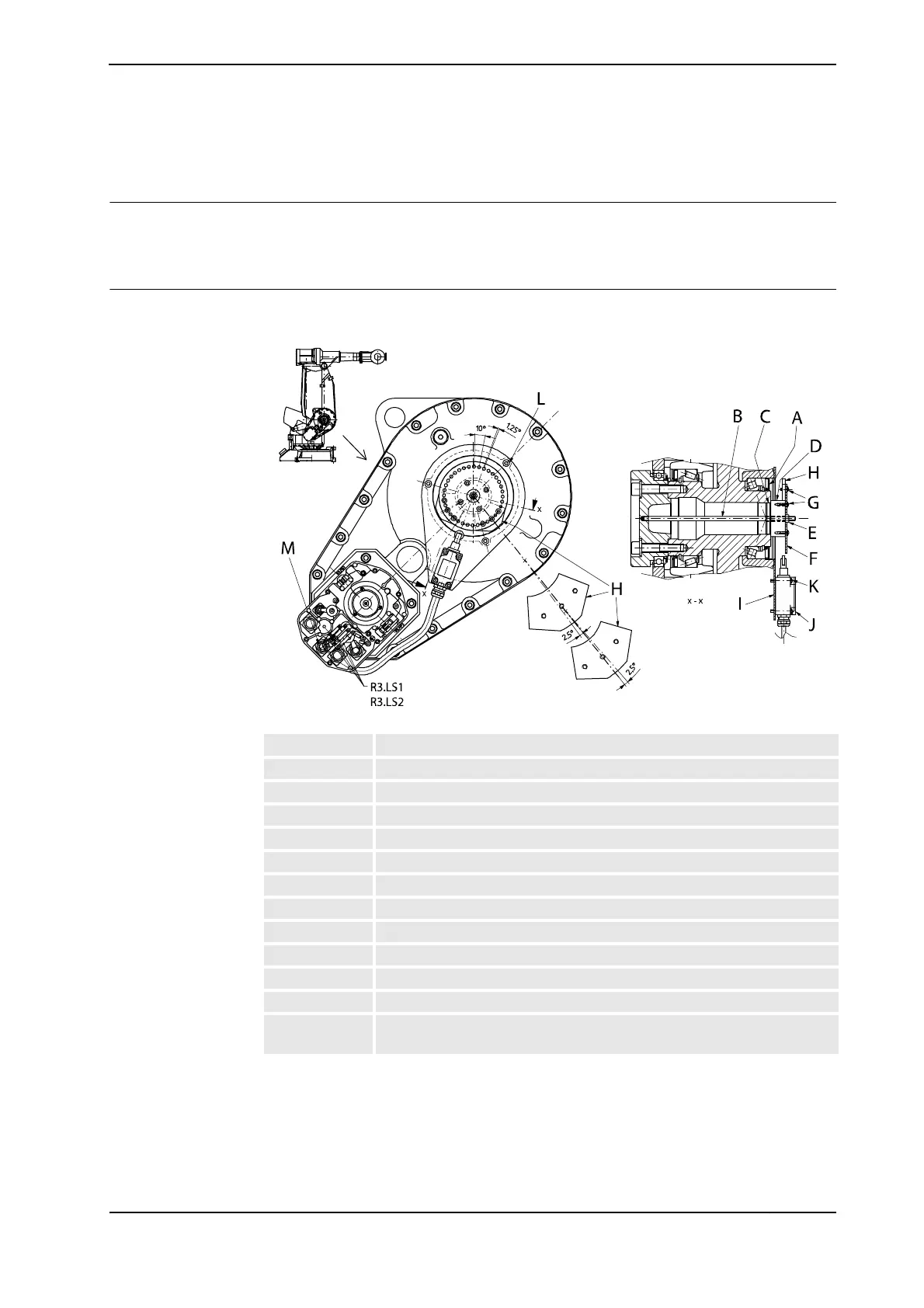
The working range of axis 3 can be limited by fitting an electric switch on the gearbox for
axis 3, which senses the current position via a cam.
Electrical stop
All the separate parts of the electrical stop are fitted to axis 3 as shown in the figure below.
xx0300000262
A Sealing with dust lip (3HAB 3701-14)
B Stud (2122 2012-867)
C All screws are locked with locking liquid
D Tap (3HAB 3798-1)
E Hexagon nut (9ADA 267-7)
F Disc (3HAB 3799-1)
G Screw (9ADA 618-44)
H Cam (3HAB 3800-1)
I Bracket (3HAB 8400-1)
J Limit switch complete (3HAB 8312-1)
K Screw (9ADA 629-50)
L Attachment screw (9ADA 183-35)
M Retaining ring (9ABA 135-18), reducing coupling (2686 015-3), washer
(2152 398-3)
Continues on next page

 Loading...


