186 | XIO USER MANUAL | 2106424MNAB
9.4.2 Local access by host
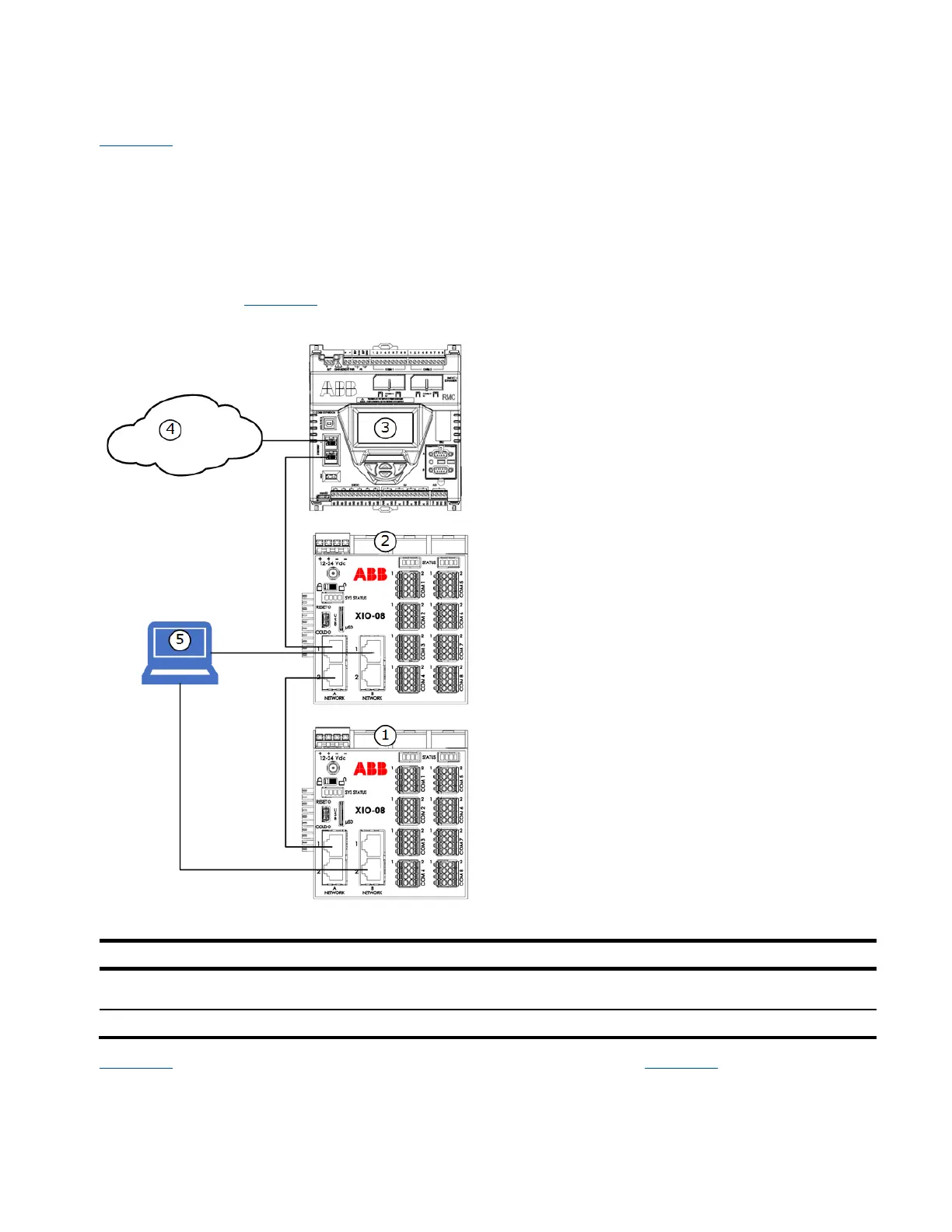
Figure 9-5 shows the connections for local access by a host for devices daisy-chained in the field. In this
example, the RMC (3) is configured as a 2-port switch (Ethernet interfaces E1 and E2 are set to 1-
Network Mode). The XIOs (1, 2) are configured as 4-port switches (Ethernet interfaces A1, A2, B1, and B2
set to 4-port switch mode). The first XIO (2) connects to the RMC with A1, and to the second XIO (1) with
A2.
To establish communication with the devices, the operator can connect the host system (5) to any of the
available ports without permanent connections. The figure shows two connections from the host as
examples, but only one physical connection is needed. When the host connects to either interface, it is
connecting to the common network the switched-mode interfaces provide. See the logical equivalent of
this configuration in Figure 9-6
.
Figure 9-5: Local access by host – supported physical connections (daisy-chain topology)
Legend: Local access by host – supported physical connections (daisy chain topology)
Host system with PCCU: local access
through XIO-1(B1) or XIO-2(B2).
Customer (TCP/IP) network
Figure 9-6 shows the logical network equivalent to the connections shown in Figure 9-5 above. A local
system with PCCU (1) can establish connections to each daisy-chained device on the same network (3).
Each device must have an IP address with the same subnet assigned to the network. The host must also
have that same subnet in its IP address. Note that connections lines on diagrams are independent logical
 Loading...