FUEL SUPPLY SYSTEM
4 -21
Pegaso 650 I.E.
4.9.7 CHECKING THROTTLE VALVE CONTROL
SHAFT END PLAY
◆ Remove the throttle body, see 4.9.2 (REMOVING THE
THROTTLE BODY).
aCAUTION
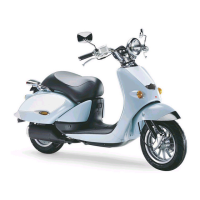
For the correct measurement of the axial clearance of
the throttle valve control shaft, it is necessary to re-
move the spring (1), the bushes (2) (3) and the two
washers (4) (5).
◆ Unscrew and remove the nut (6), taking the washer
◆ Remove, in the order indicated:
– throttle valve control lever (7);
– spring washer (4);
– bush (2);
– spring (1);
– bush (3);
– washer (5).
◆ Reassemble the throttle valve control lever (7) correct-
ly.
◆ Screw the nut (6).
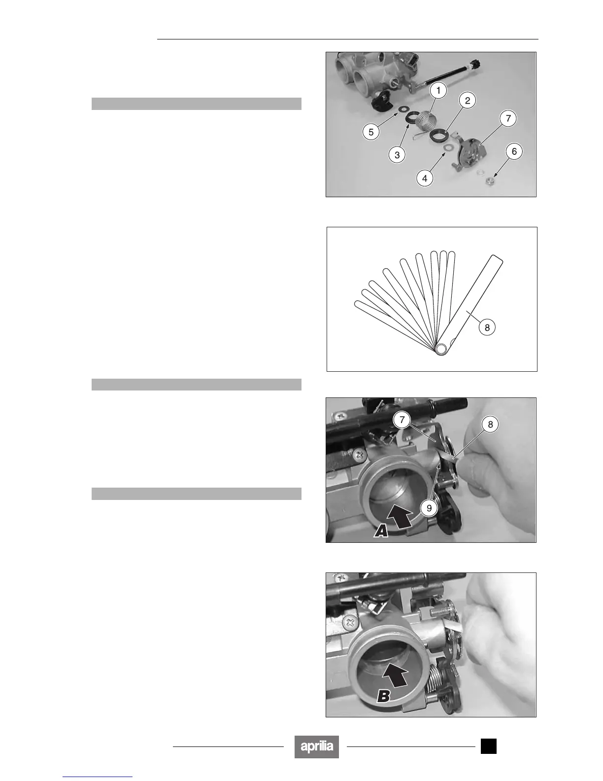
NOTE Have an appropriate thickness gauge (8) to
hand with a 0.05 mm scale.
With throttle valves closed (A):
◆ Use the thickness gauge (8) to measure the minimum
play between the lever (7) and the contact surface (9)
on the throttle body in a number of points.
End play: min. 0.1 mm.
aCAUTION
If the minimum value measured is lower than 0.1 mm,
the throttle body must be replaced, see 0.4.2 (SPARE
PARTS CATALOGUES).
With throttle valves open (B):
◆ Repeat the above procedure.
End play: min. 0.15 mm.
aCAUTION
If the minimum value measured is lower than 0.15
mm, the throttle body must be replaced, see 0.4.2
(SPARE PARTS CATALOGUES).
◆ Correctly reassemble the parts that were previously re-
moved.
Release 00/2002-02
- 00

 Loading...