ELECTRIC SYSTEM
6 -30
Pegaso 650 I.E.
,)'(43934%-
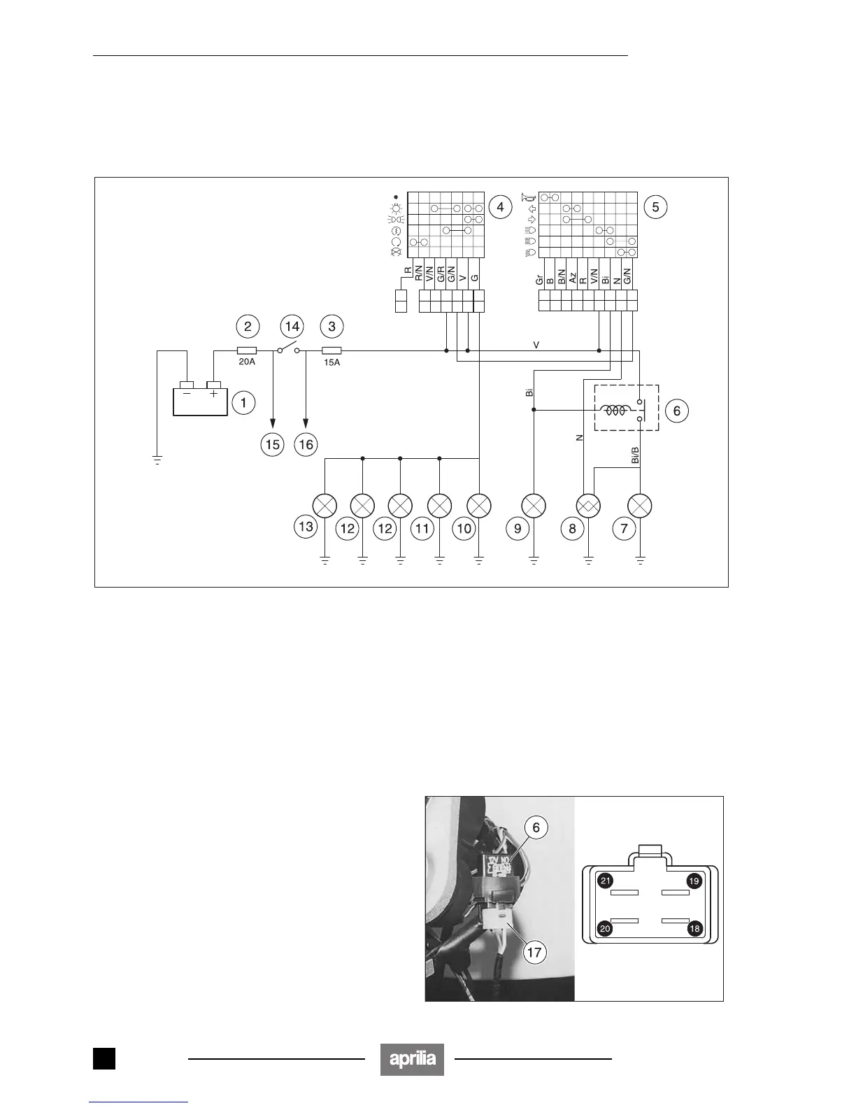
6.13.1 WIRING DIAGRAM
NOTE See 6.2 (ELECTRIC COMPONENTS LAYOUT)
for the positioning of the components.
Key:
1) Battery
2) Fuses (20 A)
3) Fuses (15 A)
4) Right dimmer switch
5) Left dimmer switch
6) High beam relay
7) High beam bulbs
8) Low/high beam bulbs
9) High beam warning light
10) Bulbs for dashboard lighting
11) Front parking light bulb
12) Rear parking light bulb
13) Number plate light
14) Ignition switch
15) To voltage regulator
16) To the injection
6.13.2 CHECKING THE HIGH BEAM RELAY
In order to check the operation of the relay:
◆ Remove the dashboard fairing, see 7.1.27 (REMOV-
ING THE DASHBOARD FAIRING).
◆ Disconnect the connector (17) from the relay (6).
◆ Power with a battery the two internal male terminals
(18) (19) at 12 V.
◆ Using a tester (set as an ohmmeter), check for breaks
between the other two terminals (20) (21).
Correct value with relay powered: 0 Ω
Correct value with relay not powered:
∞ Ω
If the resulting values do not correspond to those indicat-
ed, change the relay.
Release 00/2002-02
- 00
 Loading...