FUEL SUPPLY SYSTEM
4 -14
Pegaso 650 I.E.
4(2/44,%"/$9
aCAUTION
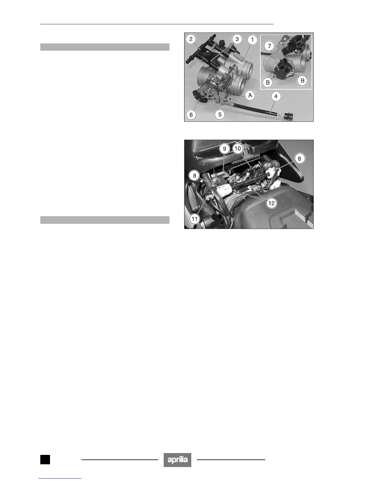
The screw for the basic setting of the throttle valves
(A) is painted and cannot be adjusted.
The two screws (B) fastening the throttle valve sen-
sor are painted and can only be removed in the event
the actual sensor is replaced.
The throttle body comprises the following units:
– throttle body (1);
– manifold (fuel rail) (2) complete with injectors (3);
– idling speed adjustment cable (4);
– throttle valve control lever (5);
– cold start lever (6);
– throttle valve sensor (7).
4.9.1 REMOVING THE INJECTORS
Carefully read 0.5.1 (PRECAUTIONS AND GENERAL
INFORMATIONS).
The removal and reassembly of the injectors can be car-
ried out with the throttle body mounted on the vehicle.
◆ Remove the saddle, see p 7.1.7 (REMOVING THE
SADDLE).
◆ Disconnect the two rapid couplings (8).
aWARNING
Mark the electrical connectors (9) (10) so as to pre-
vent them being mixed up by mistake during refitting.
◆ Disconnect the electric connectors (9) (10).
◆ Disconnect the electric connector (11) of the throttle
valve sensor.
◆ Unscrew and remove the two screws (12), taking the
washers.
◆ Remove the manifold (fuel rail) (2) together with the in-
jectors (3) from the throttle body.
◆ Release the two clip (13).
◆ Remove the two injectors (3) from the manifold (fuel
rail) (2).
Release 00/2002-02
- 00

 Loading...