ELECTRIC SYSTEM
6 -29
Pegaso 650 I.E.
&5%,,%6%,#)2#5)4
6.12.1 WIRING DIAGRAM
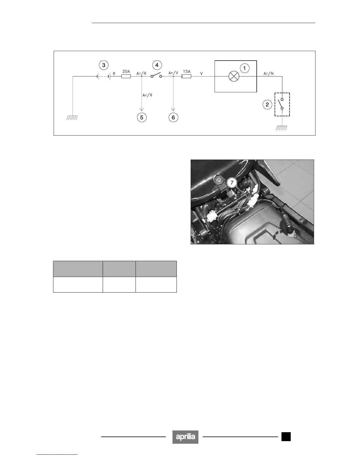
Wiring diagram key
1) Low fuel warning light (-) (coloured amber)
2) Fuel level sensor
3) Battery
4) Ignition switch (2 – 1 – &)
5) To voltage regulator
6) To ignition/injection
6.12.2 FUEL LEVEL INDICATOR
◆ Disconnect the electric connector (four-way) (7) of the
fuel pump unit (2).
Checking the operation of the low fuel warning light
◆ Directly connect (resistance 0 Ω) the orange/black ca-
bles (Ar/N) and the blue cable (B) of the connector (7)
(wiring side); make sure that the low fuel warning light
comes on.
If the low fuel warning light "-" does not come on, change
the fuel level sensor, see 4.4 (REMOVING THE FUEL
LEVEL SENSOR).
Between the
cables
Resistance
Indication
correct
orange/black (Ar/N)
- blue (B)
0 Ω warning light on
Release 00/2002-02
- 00

 Loading...