ELECTRIC SYSTEM
6 -9
Pegaso 650 I.E.
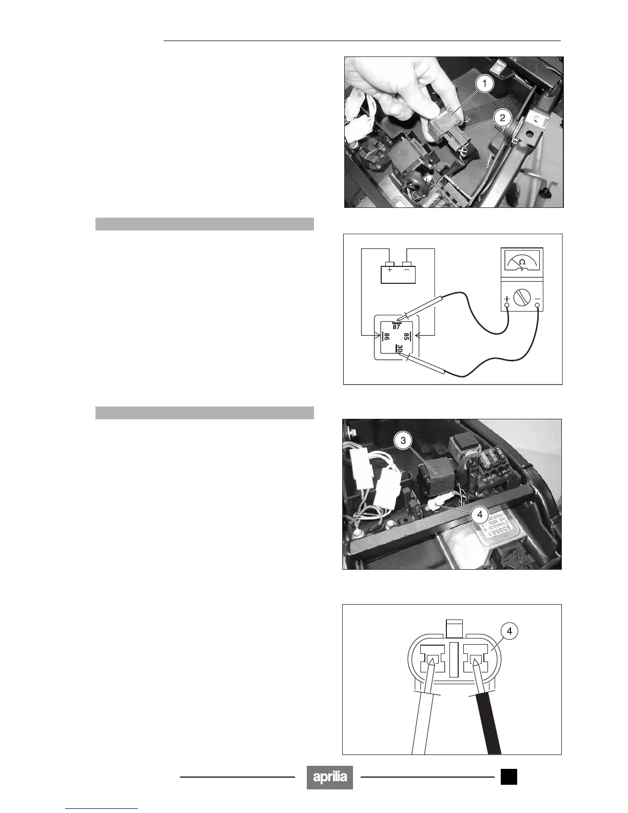
6.4.3 CHECKING THE INJECTION RELAY
In order to check the operation of the relay:
◆ Remove the saddle, see p 7.1.7 (REMOVING THE
SADDLE).
◆ Remove the injection relay (1) from its seat.
◆ Disconnect the connector (2).
◆ Power the two internal male terminals (85) (86) at 12 V.
◆ Using a tester (set as an ohmmeter), check for breaks
between the other two terminals (87) (30).
Correct value with relay powered: 0 Ω
Correct value with relay not powered:
∞ Ω
If the values do not correspond to those indicated,
change the relevant relay.
aCAUTION
Respect the polarity, supplying power with the "+"
pole to the terminal (86) and with the "–" pole to the
terminal (85), inside there is a diode.
6.4.4 CHECKING THE FALL SENSOR
With the engine switched off:
◆ Remove the saddle, see p 7.1.7 (REMOVING THE
SADDLE).
Check whether the sensor (3) is fitted correctly (with the
arrow inscribed on the rubber element pointing up).
◆ Disconnect the two-way connector (4) (coloured white/
grey) and take the measurements (on the sensor-side
terminals).
aCAUTION
Upon reassembly, make sure that the electric con-
nector (4) is correctly coupled.
◆ Using a pocket tester (scale x 100 kΩ), measure the re-
sistance between the terminals of the black and white/
black (N - Bi/N) cables.
Standard value: resistance 62 kΩ ± 15 %.
◆ Remove the sensor (3) complete with rubber element
from its housing and tilt it sideways at an angle of over
45° (simulating the condition of a vehicle resting on the
ground).
Standard value: 0 – 1 Ω.
If the resistance is any value other than that pre-
scribed, the sensor (4) must be changed.
◆ Repeat the procedure, tilting the sensor in the opposite
direction.
Release 00/2002-02
- 00