ELECTRIC SYSTEM
6 -7
Pegaso 650 I.E.
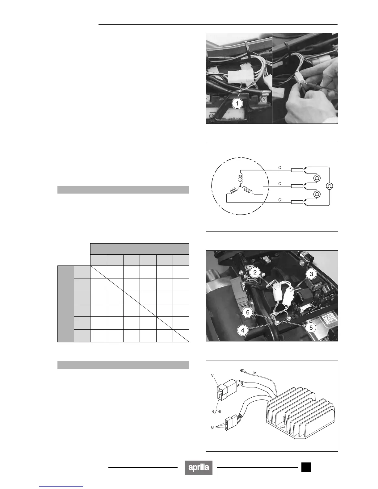
6.3.3 CHECKING THE ALTERNATOR CONTINUITY
With the engine switched off:
◆ Remove the left cover, see 7.1.4 (REMOVING THE
RIGHT AND LEFT SIDES).
◆ Disconnect the alternator cables connector (1).
◆ Using a pocket tester, check for breaks between the ca-
bles of the stator [on the internal female terminals, yel-
low cables (G)].
Also check the isolation of the stator mount.
Standard resistance value: 0.1 – 1Ω
Standard resistance value (between cables and sta-
tor mount):
∞ (infinity).
6.3.4 CHECKING THE VOLTAGE REGULATOR
◆ Remove the saddle, see p 7.1.7 (REMOVING THE
SADDLE).
◆ Disconnect the connectors (2) (3).
◆ Unscrew and remove the screw (4) and disconnect the
terminal of the cable (5) and of the cable (6) (earth ca-
bles).
aCAUTION
Upon reassembly, reconnect the cables (5) and (6).
◆ Using a pocket tester (scale x 1KΩ), measure the re-
sistance between the cables indicated in the table be-
low from the regulator side (internal male terminals).
If the resistance measured is incorrect, replace the
regulator.
aCAUTION
This measuring method is approximate; if possible,
check the correct operation of the recharging system
using another regulator in perfect condition.
Positive terminal (+) of the tester on:
G G G V R/Bi M
Negative terminal (–)
of the tester on:
G
∞∞1 – ∞∞1 – ∞
G
∞∞1 – ∞∞1 – ∞
G
∞∞ 1 – ∞∞1 – ∞
V
∞∞∞ ∞1 – ∞
R/Bi
1 –
∞ 1 – ∞ 1 – ∞ 2 – ∞ 2 – ∞
M
∞∞∞1 – ∞ 1 – ∞
Release 00/2002-02
- 00

 Loading...