ELECTRIC SYSTEM
6 -27
Pegaso 650 I.E.
#//,!.44%-0%2!452%).$)#!4/2
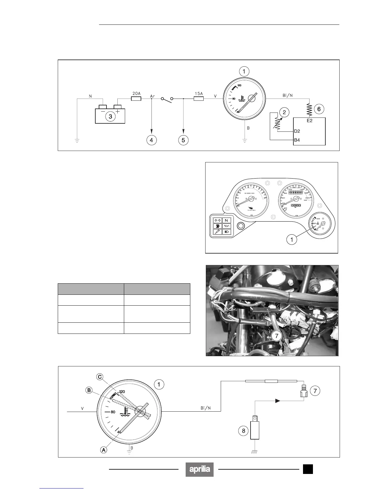
6.10.1 WIRING DIAGRAM
Wiring diagram key
1) Coolant temperature indicator ())
2) Air thermistor
3) Battery
4) To the cooling fan and voltage regulator
5) To the ignition
6) Resistance
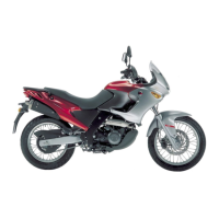
6.10.2 CHECKING THE INSTRUMENT
◆ Remove the front fairing, see 7.1.24 (REMOVING THE
FRONT FAIRING).
◆ Disconnect the connector (7) (coloured white/black Bi/
N).
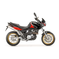
◆ Connect three 1000 ohm / 65 ohm / 0 ohm resistances
(8) in succession to the terminal (dashboard side).
◆ Turn the ignition switch to position "2".
◆ Make sure that the pointer is positioned as indicated in
the figure and in the table (A – B – C).
Resistance connected Pointer position ±3°
1000 Ω 40° C (A)
65 Ω Beginning of the red area
(B)
0 Ω > 100 °C
Release 00/2002-02
- 00