6 -8
ELECTRIC SYSTEM
Pegaso 650 I.E.
).*%#4)/.3934%-
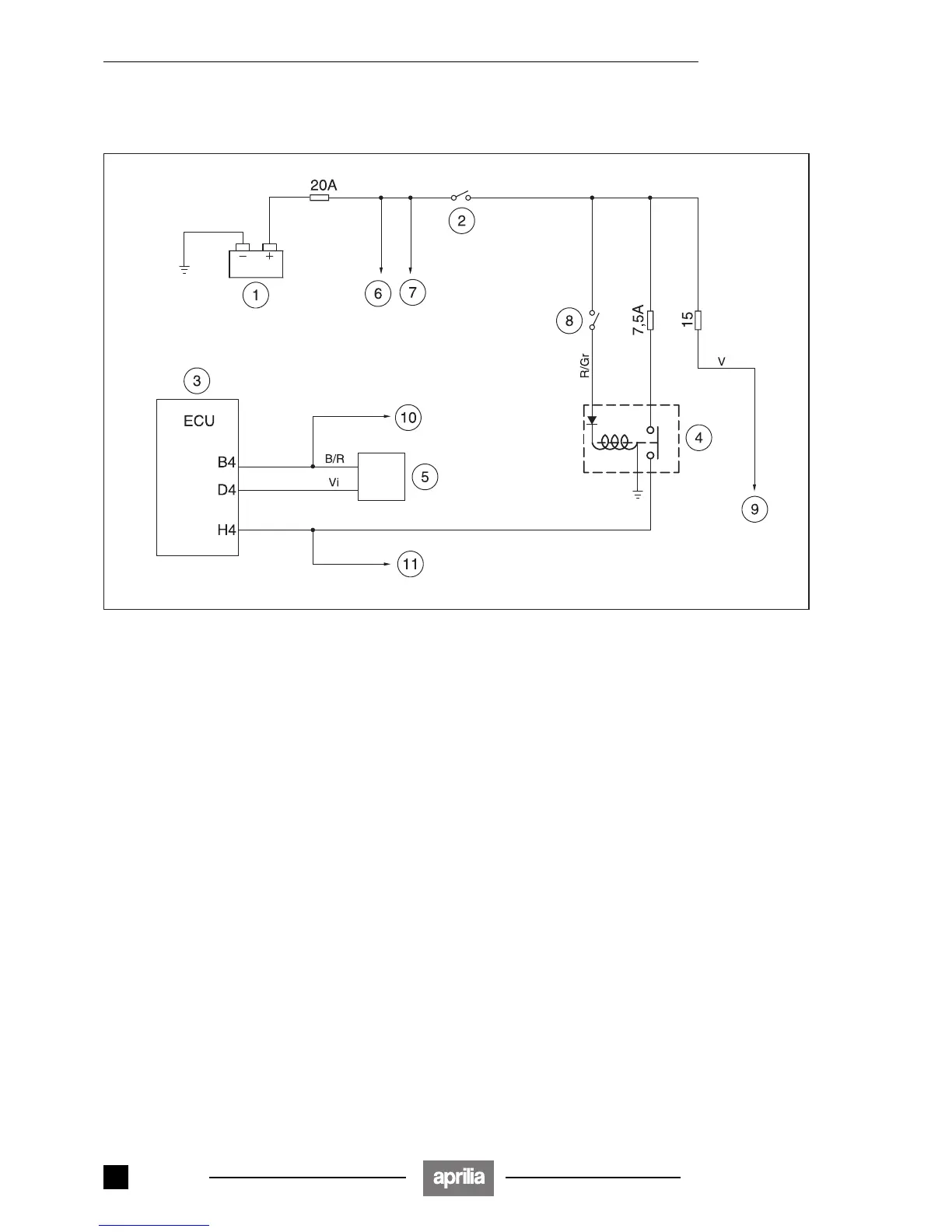
6.4.1 INJECTION POWER SUPPLY DIAGRAM
Key
1) Battery
2) Ignition key
3) Unit
4) Injection relay
5) Fall sensor
6) To voltage regulator
7) To the cooling fans
8) Kill switch
9) Light loads
10) To the water temperature thermistor, the air
temperature thermistor, the accelerator sensor.
11) Fuel pump, injectors, coil power supply.
6.4.2 TROUBLESHOOTING
◆ Make sure that the 20 A main fuse and the 7.5 A fuse
are in good condition.
◆ Verify the correct operation of the Kill switch device,
see 6.7 (IGNITION SAFETY SYSTEM) and of the key,
see 6.5 (IGNITION/INJECTION SYSTEM).
◆ Check the injection relay, see 6.4.3 (CHECKING THE
INJECTION RELAY).
◆ Check the fall sensor, see 6.4.4 (CHECKING THE
FALL SENSOR).
- 00
Release 00/2002-02
 Loading...