FUEL SUPPLY SYSTEM
4 -16
Pegaso 650 I.E.
4.9.2 REMOVING THE THROTTLE BODY
Carefully read 0.5.1 (PRECAUTIONS AND GENERAL
INFORMATIONS).
◆ Remove the fuel tank, see 7.1.1 (REMOVAL OF THE
FUEL TANK).
◆ Partially remove the saddle support, see 7.1.36 (RE-
MOVING THE SADDLE SUPPORT).
aWARNING
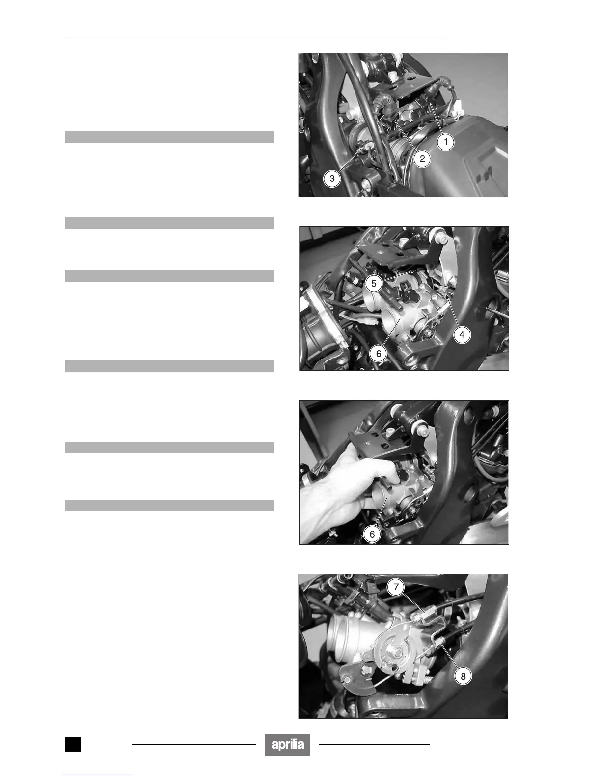
Mark the electrical connectors (1) (2) so as to prevent
them being mixed up by mistake during refitting.
◆ Disconnect the electric connectors:
– right injector (1);
– left injector (2);
– throttle body sensor (3);
aCAUTION
When reassembling, make sure the electric connec-
tors are plugged in properly.
◆ Loosen the two clamps (4) (5).
aCAUTION
Proceed with care.
Do not force the cables.
The throttle body (6) remains constrained to the ac-
celerator cable and to the cold start cable.
◆ Grip the throttle body (6) firmly and hitch it one way and
the other slide it off the intake flanges.
◆ Disconnect the throttle cable (7).
aCAUTION
Upon reassembly, make sure that the accelerator
control cable regulator is correctly fastened to the
corresponding coupling, then check and if necessary
adjust the slack, see 2.9.3 (ADJUSTING THE ACCEL-
ERATOR CONTROL).
◆ Disconnect the cold-start control cable (8).
aCAUTION
When reassembling, make sure the cold-start control
cable adjuster is properly fastened to the respective
coupling and check and, where necessary, restore
the correct freeplay, see 2.10 (COLD START CABLE).
aCAUTION
Upon reassembly:
– the throttle body (6) must be fitted perfectly on the
intake flanges;
– the clamps (4) (5) must be properly tightened.
– do not invert the position of the electrical connec-
tors (1) (2).
Release 00/2002-02
- 00

 Loading...