8. Light processor assembly
8.8 Electrical c onnections
Preparations
Guide all cables to the connector side of the backplane.
Formatter connections
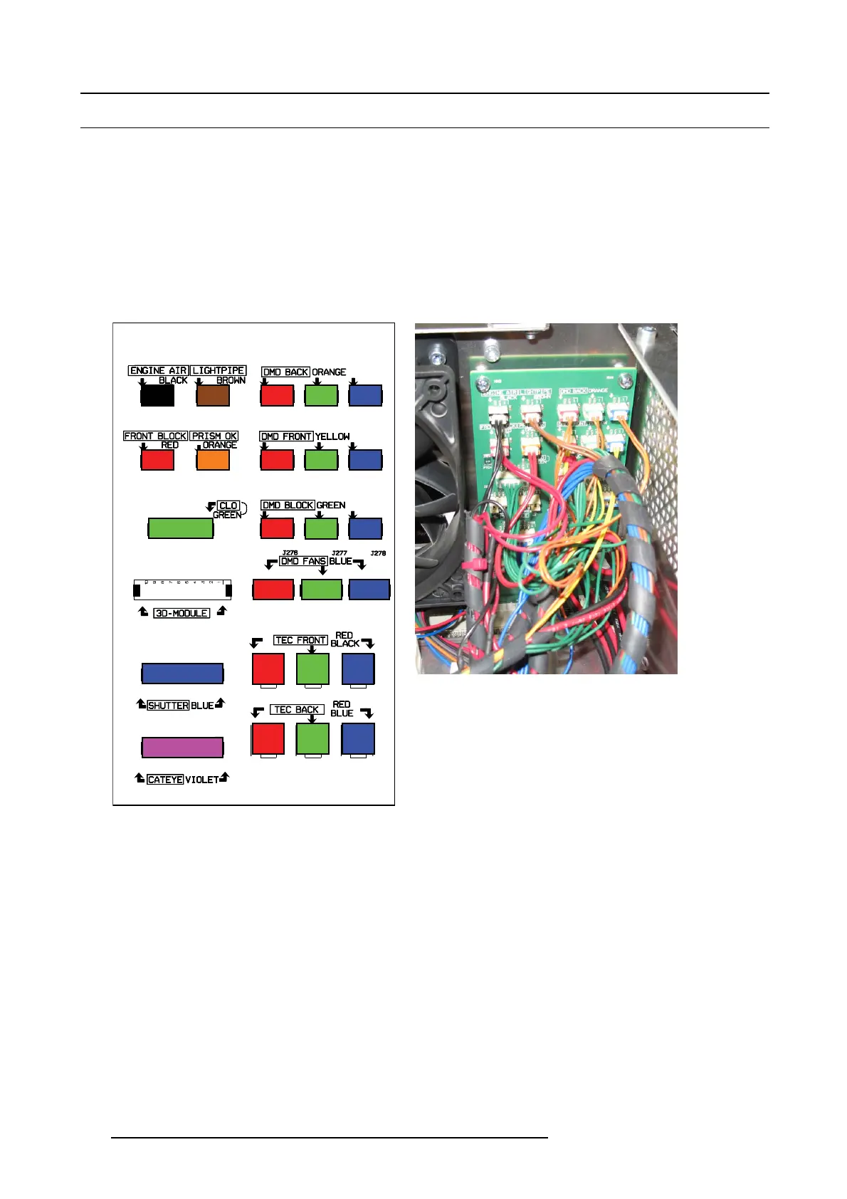
All formatter cables, data and power, have a colored cable tie. T here are 2 cables per color available, both with a different connector.
The color nam e is screen on the printed circuit board. P lug in the cable with e.g. a red cable tie into the connector with the same
size and with the indication re d. Repeat for all other cables.
Other connections (right si de)
Color conv ention for the connections.
J278
J272
J271
J274 J275
J282
J279
J291
J251
J254
J260
J250
J270
J273
J276
J253
J283
J14
J262
J255J252
J261
J277
J280
J281
Image 8-12
Color coding cables
Image 8-13
Color coding cables, image
The color indication on the socket corresponds with the colored cable tie on the cable n ext to the connector.
The screened c olor indication just above the sock ets corresponds with the color of the wires in the cable tree.
146
R5905043 DP2K-12C/11CX 19/02/2018
 Loading...


