17. Lamp power supply
17.1 Introduction
Functionality of t he Lamp Power Supply
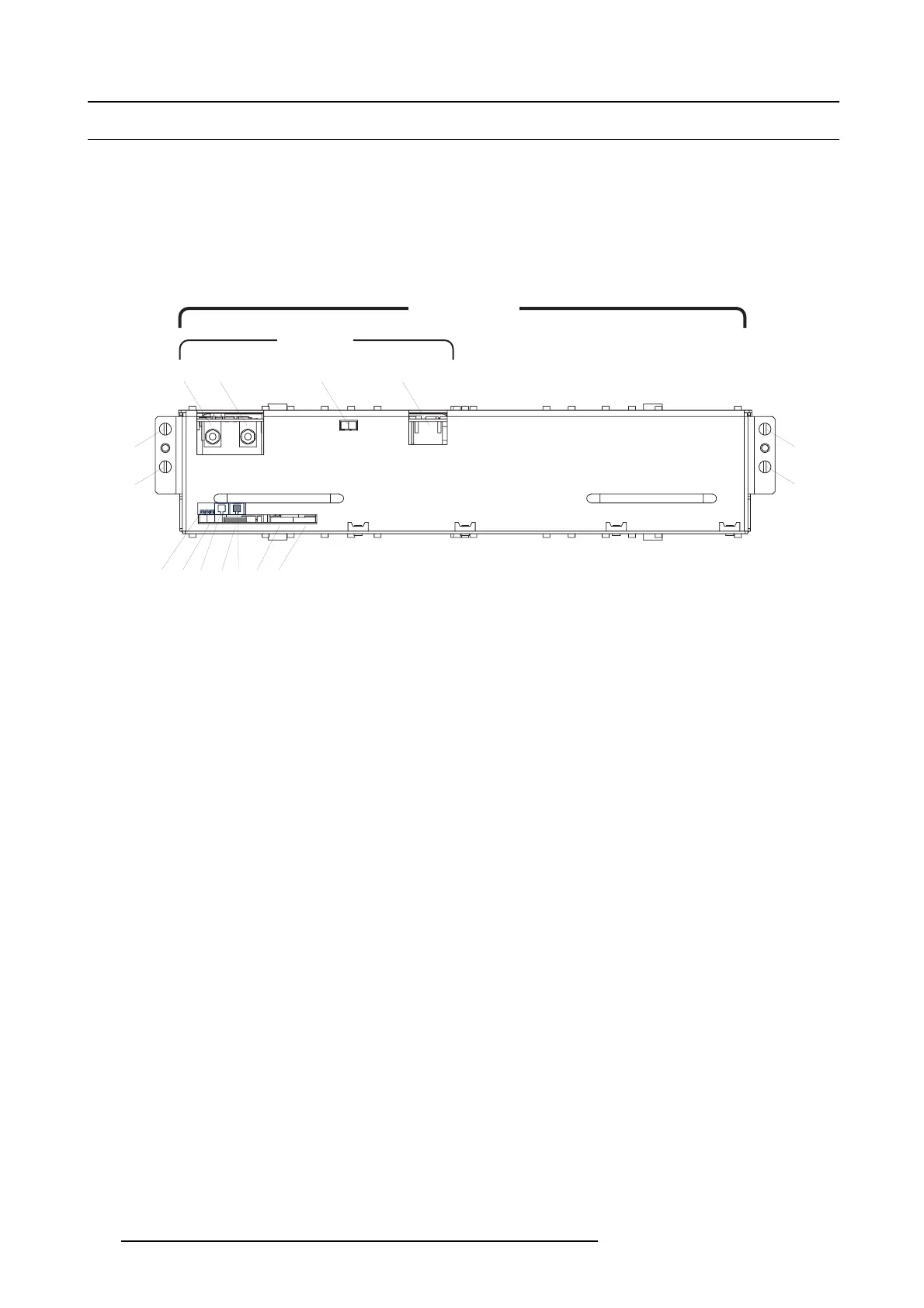
The front s ide of the LPS cas ing contains the input/output connectors and diagno stic LED’s of the LP S unit. The rear side is equipped
with fans. T he whole LP S module slides into the LPS compartment at the rear bottom of the projector and can b e replac ed ea sily.
To ignite the lamp the voltage on the output pins of the LPS unit is brought up to 140 volt. This high voltage will trigger the Start
Pulse Generator (SPG) to ignite the lamp. Once the lamp is ignited the voltage o n the output pins of the LPS unit is dropped to the
typical arc voltage of the lamp.
Parts
B
G
C D
K LI
E
A
A
LAMP OUT
MAINS
INPUT
LPS UNIT 1
LPS MODULE
F H J
Image 17-1
A Captive screw. G Status LEDs: “ERR ”, “ PF C OK” & “LPS OK”.
B Lamp output pin “–”. H Socket for “CTRL OUT” cable - DP2K series.
C Lamp output pin “+”. I Socket for “AD DRES S” cable.
D Status LEDs: “ LAM P O N / LVPS O K ”. J Socket for CTRL IN” cable - DP2K series
E Mains input. K S ocket for “CT RL OUT” cable - not used in DP2K series.
F Status L EDs, left and middle LED for internal use,
right LE D : heartbeat
L
Socket for C TRL IN” cable - not used in DP2K series
284
R5905043 DP2K-12C/11CX 19/02/2018
 Loading...


