11. Lenses and Lens holder
11.8 Scheimpflug adjustment
What has to be done ?
The lens holder has to be adjusted so that the “sharp focus plane” of the projected image falls together with the plane of the screen
(Fp1→Fp2). This is achieved by changing the distance between the DMD plane and the lens plane (Lp1→Lp2). T he c loser the lens
plane comes to the DMD plane the further the shar p focus plane will be. It can som etimes happ en that you won’t be able to get a
complete focused image on the screen due to a tilt (or swing) of the lens plane with respect to the DMD plane. This is also kn own
as Sheimpflug’s law. To solve this the lens plane mus t be p laced parallel with the DM D plane. T his can be a chieved by turning the
lens holder to remove the tilt (or swing) between lens plane and DMD plane (Lp3→Lp4) .
SCREEN
DMD
Lp1
Lp2
Fp1
Fp2
SCREEN
DMD
Lp3
Lp4
Fp3
Fp4
(Scheimpflug)
Image 11-17
Scheimpflug principle
Scheimpflug principle
The "plane of sharp focus" can be changed so that any plane can be brought into sharp focus. When the DM D plane
and lens plane are parallel, the plane of sharp focus will also be parallel to these two planes. If, however, the lens
plane is tilted with r espect to the D MD plane, the plane of sharp focus will also be tilted ac cording to geometrical and
optical properties. The DMD plane, the principal lens plane and the sharp focus plane will intersect in a line below the
projector for downward lens tilt.
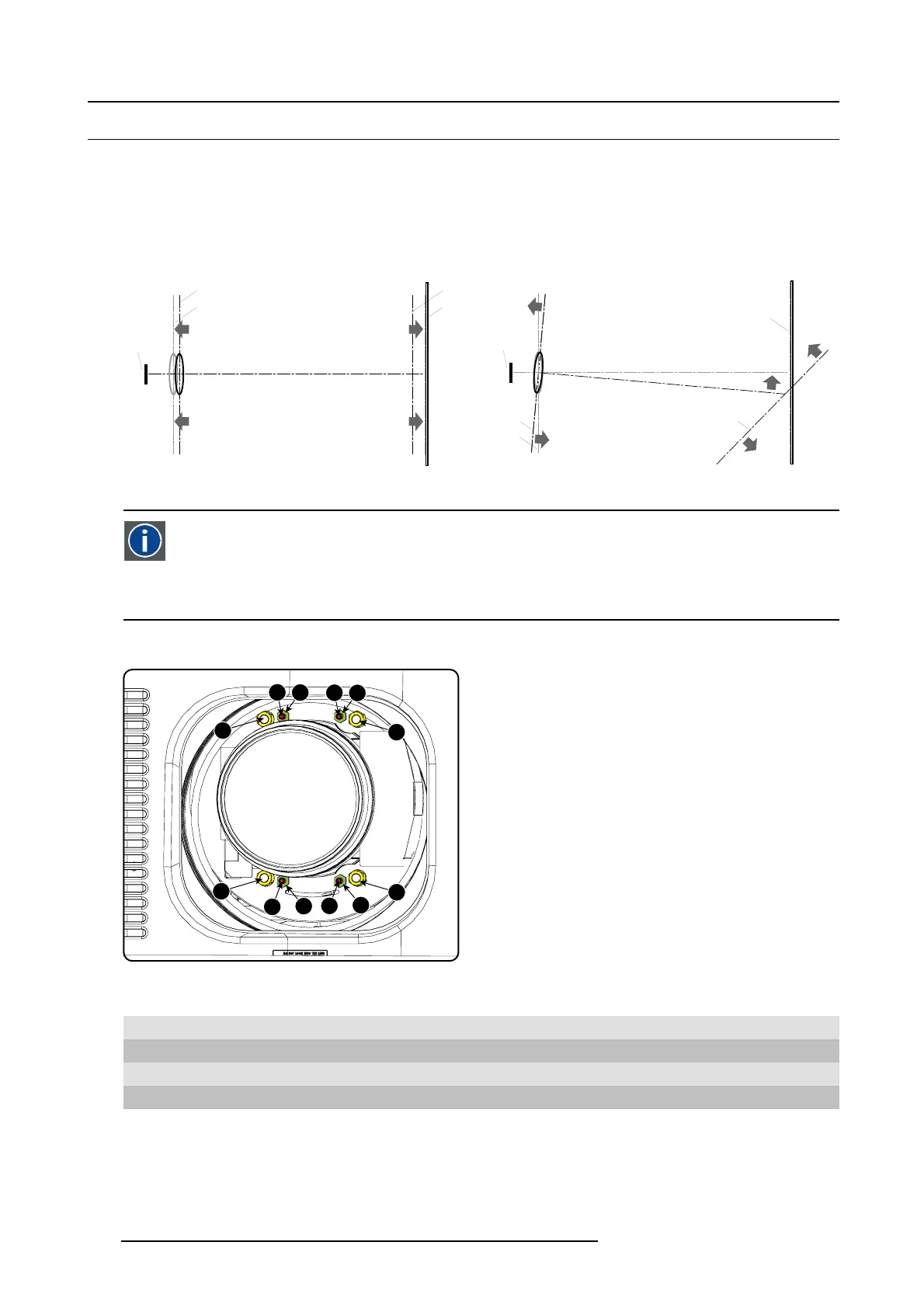
Scheimpflug adjustment points
4
1
2
3
d
D
c
C
A
a
B
b
Image 11-18
Scheimpflug adjustments
Indication on drawing Function
4 Locking nut
1, 2 and 3
Scheimp flug adjustment nuts
A, B, C and D Set screws
a, b, c and d lock nuts
1, 2 and 3 are adjustment points.
4 is a locking point and NOT us ed during Scheimpflug adjustment.
192
R5905043 DP2K-12C/11CX 19/02/2018
 Loading...


