10. Integrator rod
6. Turn the lower nut of the folding mirror until the upper and left edge of the rod can be seen on the screen.
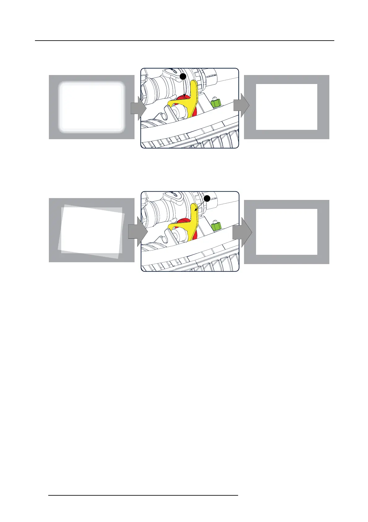
7. Gently rotate ring 2 back or f orward to a pos ition w hich projects the sharpest possible edges on the screen.
2
Image 10-13
8. Gently move the handle 3 back or forward to a position so that the projected light beam m atches the projected outline of t he
DMD’s
Note: No spots in the projected image may move along with the movements of the rod. Spots w hich m ove with the m ovements
of the rod indicates that the exit side of the integrator r od is contaminated with dust. If this is the c ase, remove the
integrator rod and try to blow away the dust. If this does n’t help replace the integration rod.
3
Image 10-14
9. Fasten the lock nut (1) w ith a torque of 2Nm.
10.Turn the lower nut of the folding mirror back to its original position (see alignment procedure of the folding m irror for th e correct
alignment)
11.M ount the Fold Mirror cover and the Light Sensor Module.
178
R5905043 DP2K-12C/11CX 19/02/2018
 Loading...


