19. Start Pulse Generator
Image 19-8
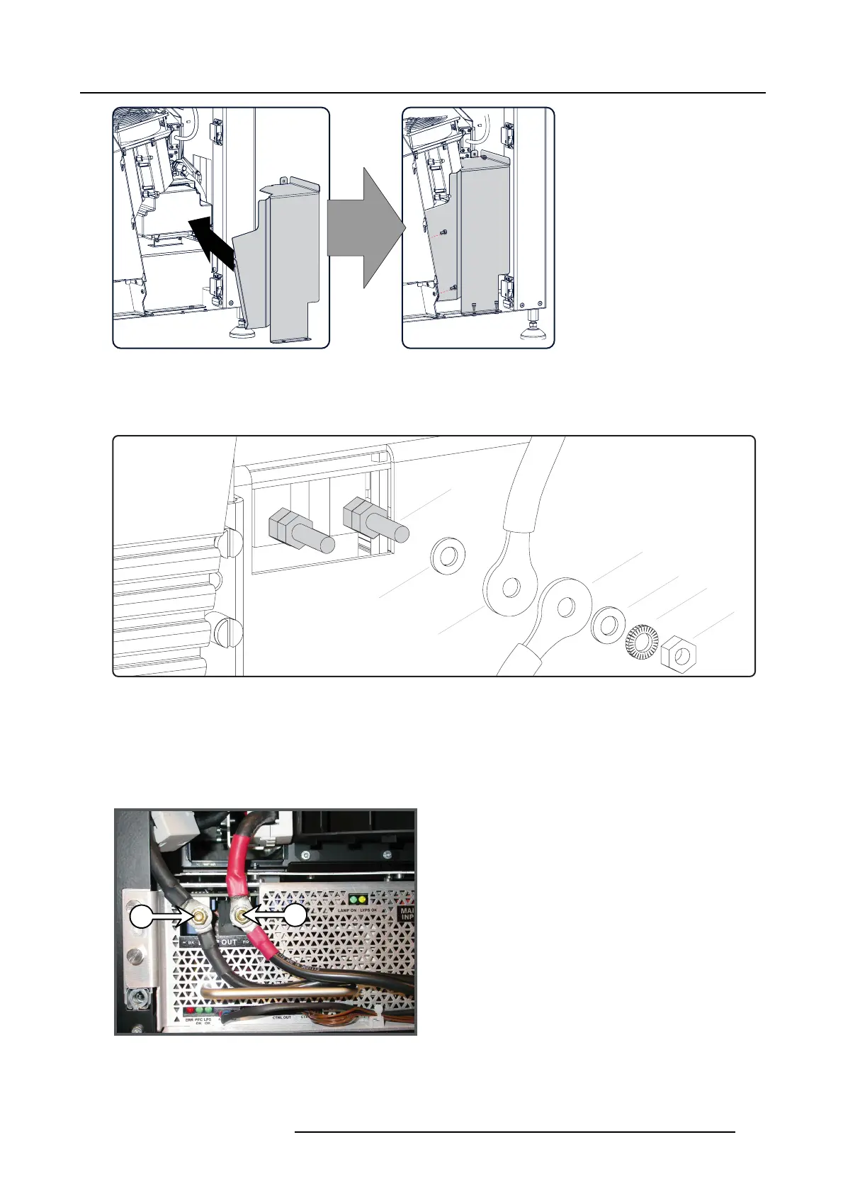
4. Connect the power cables coming from the Start Pu lse Generator with the “LAM P O UT” s ocket
s of the LPS mod ule as illustrated.
Fasten the nuts with a torque of 4Nm (2.95 lbf*ft).
Warning: Make su re to p lace the w ashers and cable eyes in correct order upon the pin as illustrated. Alw ays u se a plain
washer between the output pin and the cable eyes.
E2
L
N
P
W
E1
W
Image 19-9
Lamp out connection
P LPS output pin.
W Plain w asher.
L Lock washer.
E1 Ca b le eye from SPG m o dule .
E2 Cable eye from LPS unit.
NNut.
Warning: Respect the polarity of the socket and cables. Red marked cables with the “+” pin, black marked c ables with the “-”
pin.
-
+
Image 19-10
Warning: Make sure that both SPG cables ar e provided with ferrite blocks (C). Reuse the ferrite b locks of the removed SPG
module in cas e no ferrite blocks are present upon the installed SP G module.
R5905043 DP2K-12C/11CX 19/02/2018
309
 Loading...


