6. Input & communication
6.4 About General Purpose Inputs & Outputs (GPIO)
General Purpose inputs
Eight (8) opto-isolated gener al purpose inputs are available, six (6) free an d 2 dedicated inputs. These inputs are used to trigger the
execution of macro files. For more ex planation about the association of a macro to a GPI, consult the user guide of the Comm unicator
touch panel.
Input voltage
The inputs can be directly driven from a TTL or CMOS output.
• Minimum voltage : V
min
=3,3V
• Maximum voltage : V
max
=24V
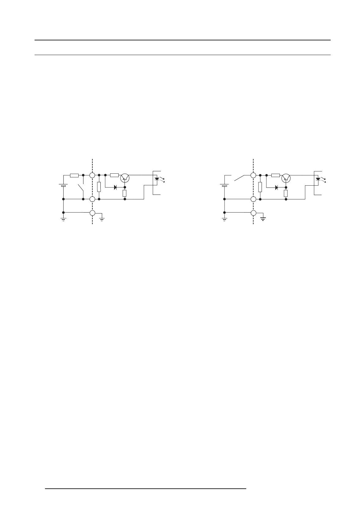
External power supply
When interfacing with contact closure outputs, an external power supply needs to be provided. Depending upon the configuration a
suitable pull-up resistor needs to be added as well.
100R
GPIn P
GPIn N
10k
Input to projector Internal projector
1k1
+5V
to
+24V
Input to projector
+5V
to
+24V
100R
GPIn P
GPIn N
10k
Internal projector
1k1
Image 6-4
Cables
When long cable connections are required the us e of shielded c ables with twisted pairs is recommended. One twisted pair is to be
assigned to each G P Input pair.
How to make the connection
When the power supply used to provide the DC voltage is is olated from ground (for example in the case of an AC adapter) it is
recommended that the minus pole of that power supply is connected to ground (or to the projector chassis). T his w ill avoid high
common mode voltages at the projector GP Inputs. If that same power supply is used for other parts of the system, take care not to
create ground loops. In any c ase when sh ielded c ables are used that shield s hould be connected to the projector chassis.
General Purpose outputs
Eight (8) opto-isolated outputs are available, where seven are general purpose and one for a fix ed purpose. The s even g eneral
purpose outputs can be controlled via software while the fixed outp ut provides the 3D output reference. W hen this output is closed
(current is flowing), then the system is OK.
About an output
The output can generate a falling ed ge, rising edge, toggle or c ontinuous toggle.
• Generate Falling Edge – generate a falling edge on the ex ternal GPO port if the present state of the output is h igh. If the
present state of the external GP O is low, no edge will be generated.
• Generate Rising Edge – generate a r ising edge on the external GP O p ort if the present s tate of the output is low. If the present
state of the ex ternal GP O is high, no edge will be gene rated.
• Generate Toggle – generate a toggle on the external GPO port. If the present state of the ou tput is low, a rising edge will be
generated, followed by a falling edge. If the present state of the ou tput is high, a falling e dge will be generated, followed by a
rising edge. T he rate of toggle will be the ver tical sync rate (edge transition at each vsync).
• Generate Continuous Toggle - This comm and will generate a continuous toggle of the external GPO por t. This toggle will
continue until a Generate F alli
ng Edge, G enerate Rising Edge,orGenerate Toggle comm and is received. T he rate of toggle
will be the vertical sy nc rate (edge transition at eac h vsync).
Output transistor
• Maximum output driving voltage : V
max
=70V
• Maximum current : I
max
=30mA
• Maximum power dissipation : 120 m W
62
R59770351 DP2K-20C 02/02/2010