EasyManua.ls Logo

Beckhoff TwinSAFE logic FB User Manual

Beckhoff TwinSAFE logic FB
217 pages
To Next Page IconTo Next Page
To Previous Page IconTo Previous Page
Page #125 background imageLoading...
Page #125 background image
Function blocks
Function blocks for TwinSAFE logic components 123
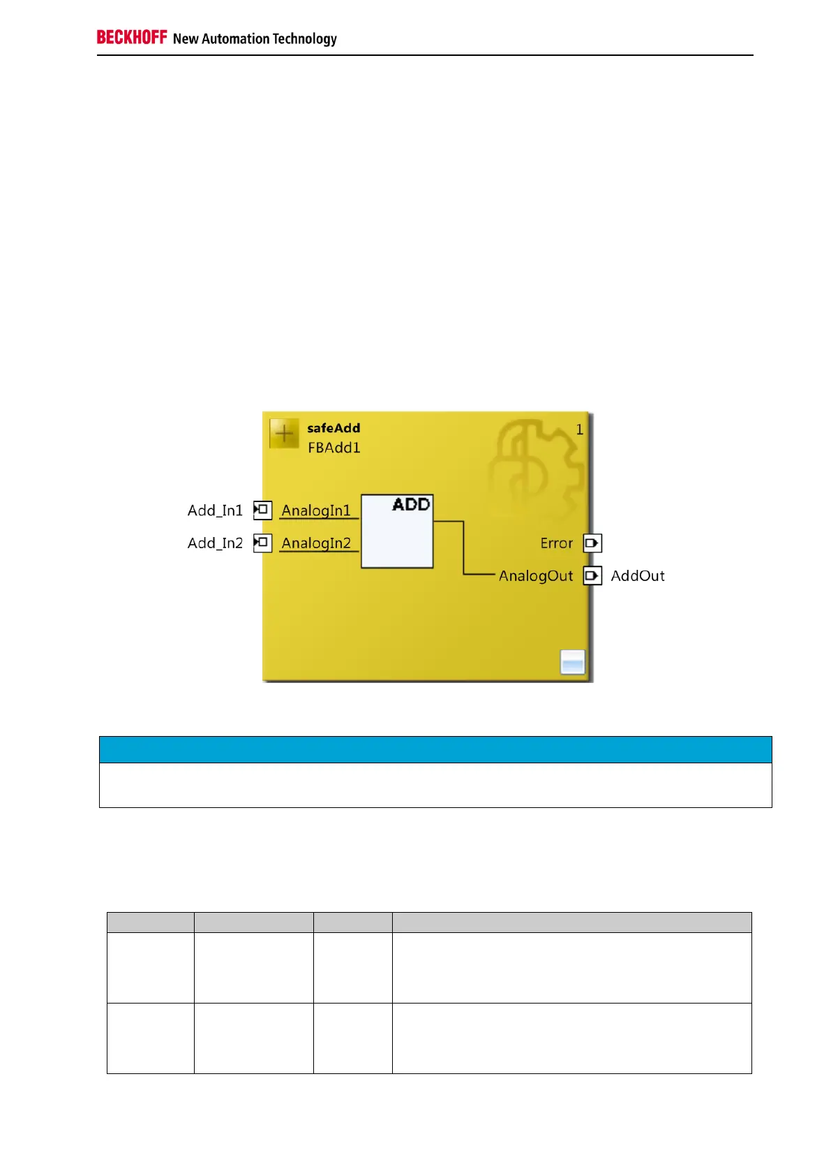
3.16 The function block ADD
3.16.1 Functional description
The FB ADD is used to add the two connected analog input values and transfer them to the AnalogOut
output. The input data types INT16, INT32, UINT16 and UINT32 are permitted. The output must be
selected to match the input types.
If an overflow or underflow occurs during the addition, the ERROR state is assumed. The AnalogOut
output is then set to 0, the Error output is set to 1.
Once overflow or underflow no longer occurs after an error, the function block can be set to RUN state
again via ErrAck of the TwinSAFE group. The RESET state is assumed when the ErrAck input of the
corresponding group is 1. When the ErrAck input of the corresponding group changes to 0 again, the
system switches from RESET state to RUN state. In RESET state the AnalogOut output and the Error
output are 0.
Figure 3-68: Function block ADD
NOTE
KL6904/EL6900
The function block ADD is not available in the KL6904 and the EL6900.
3.16.2 Signal description
Table 3-92: FB ADD inputs
Name
Permitted type
Data type
Description
AnalogIn1
TwinSAFE-In
FB-Out
Standard-In
TwinSAFE SC
INT16
INT32
UINT16
UINT32
1st input channel for addition
AnalogIn2
TwinSAFE-In
FB-Out
Standard-In
TwinSAFE SC
INT16
INT32
UINT16
UINT32
2nd input channel for addition

Table of Contents

Question and Answer IconNeed help?

Do you have a question about the Beckhoff TwinSAFE logic FB and is the answer not in the manual?

Beckhoff TwinSAFE logic FB Specifications

General IconGeneral
BrandBeckhoff
ModelTwinSAFE logic FB
CategoryIndustrial Electrical
LanguageEnglish

Summary

1 Foreword

Notes on the Documentation

Information regarding the documentation's target audience, origin, currentness, and symbols used.

Safety Instructions

Guidance on safety instructions, delivery state, operator diligence, and explanation of notes.

2 System Description

TwinSAFE Logic Terminals and Connections

Details on TwinSAFE logic terminals, groups, connections, and configuration. Includes diagnosis overview.

System Diagnosis

Information on diagnosing TwinSAFE system components, including diagrams for TwinCAT 2 and TwinCAT 3.

3 Function Blocks

The Function Block AND

Functional description, signal details, diagnostic info, and TwinCAT configuration for the AND logic block.

The Function Block OR

Functional description, signal details, diagnostic info, and TwinCAT configuration for the OR logic block.

The Function Block OPMODE

Description of OPMODE function block for operation mode selection and restart behavior.

The Function Block ESTOP

Details on ESTOP function block: description, signals, configuration, restart behavior, and extensions.

The Function Block MUTING

Description of MUTING block, signals, configuration, examples, and extensions for EL/EJ6910.

The Function Block TON

Functional description, signal details, diagnostic info, and TwinCAT configuration for the TON delay timer.

The Function Block TOF

Functional description, signal details, diagnostic info, and TwinCAT configuration for the TOF delay timer.

The Function Block ADD

Description of ADD block for analog addition: signals, diagnostics, and TwinCAT configuration.

The Function Block SUB

Description of SUB block for analog subtraction: signals, diagnostics, and TwinCAT configuration.

The Function Block COMPARE

Description of COMPARE block for analog input comparison, including architectures, signals, and config.

The Function Block LIMIT

Description of LIMIT block for checking analog input values against Min/Max limits, including signals and config.

The Function Block COUNTER

Description of COUNTER block for up/down counting: signals, diagnostics, and TwinCAT configuration.

The Function Block CAMMONITOR

Description of CAMMONITOR block for electronic cam control: modes, inputs, outputs, parameters, and diagnostics.

4 Appendix

Beckhoff Support and Service

Information on contacting Beckhoff for technical support, system solutions, and after-sales service.

Beckhoff Headquarters Information

Contact details, phone, fax, email, and web address for Beckhoff Automation GmbH & Co. KG.

Related product manuals