EasyManua.ls Logo

Beckhoff TwinSAFE logic FB User Manual

Beckhoff TwinSAFE logic FB
217 pages
To Next Page IconTo Next Page
To Previous Page IconTo Previous Page
Page #47 background imageLoading...
Page #47 background image
Function blocks
Function blocks for TwinSAFE logic components 45
In the FB error state, the outputs assume the safe state "0", only the Error output is "1".
The characteristics for acknowledging a discrepancy error can be set via the checkbox Safe Inputs after
Disc Error. If the checkbox is checked, both inputs of the input group that has caused the discrepancy
error have to switch to safe state simultaneously before the error can be reset.
3.4.2 Signal description
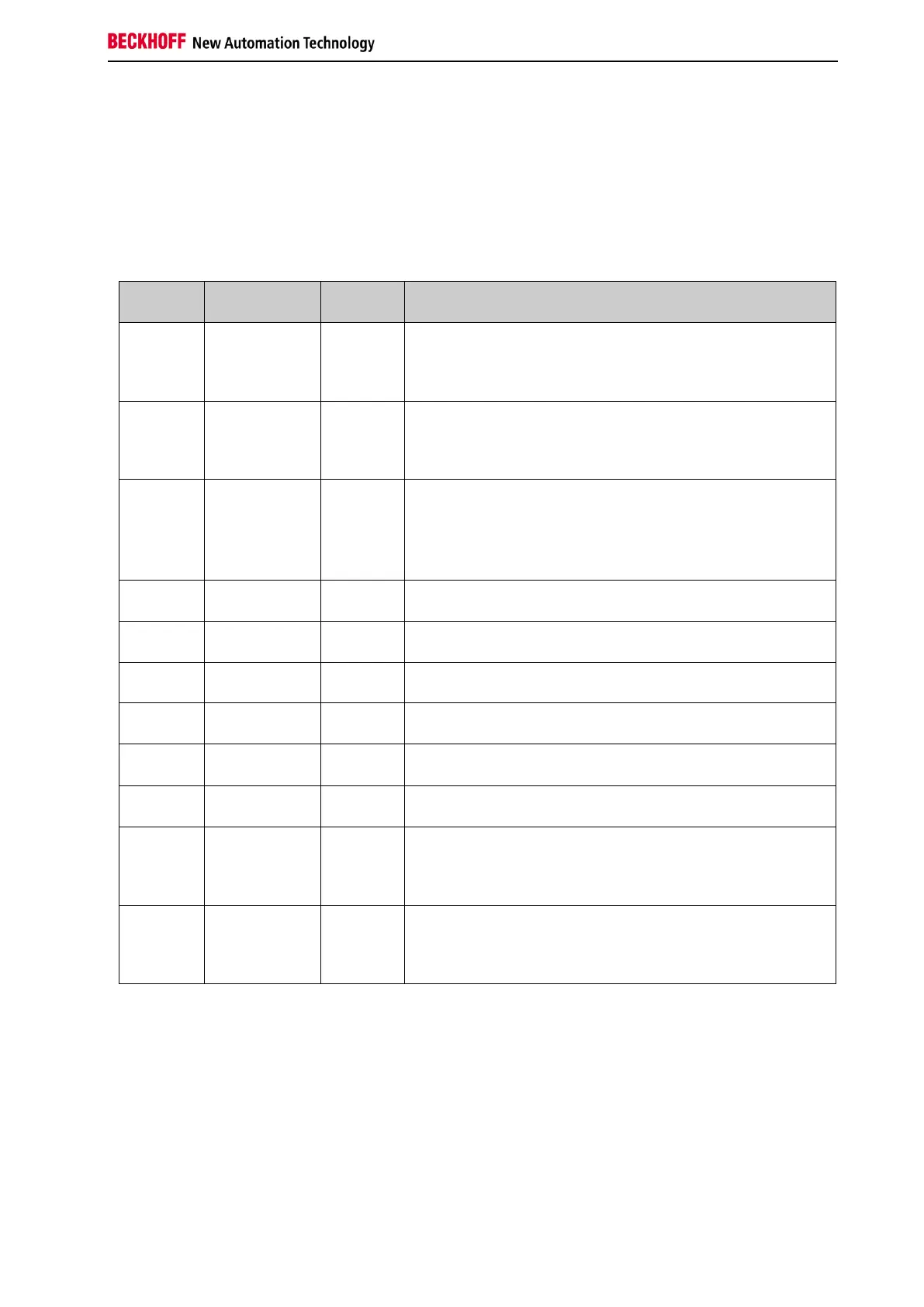
Table 3-19: FB ESTOP inputs
Name
Permitted
type
Data
type
Description
Restart
TwinSAFE-In
FB-Out
Standard-In
BOOL
During start-up (when the corresponding TwinSAFE group
is started) or a restart (when an input has requested the
safe state), a falling edge must be detected at the Restart
input before the safe state of the outputs is canceled.
EStopIn1
TwinSAFE-In
FB-Out
BOOL
1st input channel: The parameterization determines,
whether the input will be a break contact (safe state will be
requested by logical 0) or make contact (safe state will be
requested by logical 1).
EStopIn2
TwinSAFE-In
FB-Out
BOOL
2nd input channel, behaves like EStopIn1
If the discrepancy time is not equal 0, the 1st and 2nd input
channel are considered to be the 1st input pair and a
discrepancy time monitoring is carried out between both
channels.
EStopIn3
TwinSAFE-In
FB-Out
BOOL
3rd input channel or 1st input channel of the 2nd input pair,
otherwise corresponds with EStopIn1
EStopIn4
TwinSAFE-In
FB-Out
BOOL
4th input channel or 2nd input channel of the 2nd input pair,
otherwise corresponds with EStopIn2
EStopIn5
TwinSAFE-In
FB-Out
BOOL
5th input channel or 1st input channel of the 3rd input pair,
otherwise corresponds with EStopIn1
EStopIn6
TwinSAFE-In
FB-Out
BOOL
6th input channel or 2nd input channel of the 3rd input pair,
otherwise corresponds with EStopIn2
EStopIn7
TwinSAFE-In
FB-Out
BOOL
7th input channel or 1st input channel of the 4th input pair,
otherwise corresponds with EStopIn1
EStopIn8
TwinSAFE-In
FB-Out
BOOL
8th input channel or 2nd input channel of the 4th input pair,
otherwise corresponds with EStopIn2
EDM1
TwinSAFE-In
FB-Out
Standard-In
BOOL
EDM1 is the feedback loop for the non-delayed output
channel (EStopOut). If this input is parameterized as active,
the safe state of the outputs will only be exited during
restart, when the EDM1 supplies the "1" signal.
EDM2
TwinSAFE-In
FB-Out
Standard-In
BOOL
EDM2 is the feedback loop for the delayed switching of the
output channel (EStopDelOut). If this input is parameterized
as active, the safe state of the outputs will only be exited
during restart, when the EDM2 supplies the "1" signal.

Table of Contents

Question and Answer IconNeed help?

Do you have a question about the Beckhoff TwinSAFE logic FB and is the answer not in the manual?

Beckhoff TwinSAFE logic FB Specifications

General IconGeneral
BrandBeckhoff
ModelTwinSAFE logic FB
CategoryIndustrial Electrical
LanguageEnglish

Summary

1 Foreword

Notes on the Documentation

Information regarding the documentation's target audience, origin, currentness, and symbols used.

Safety Instructions

Guidance on safety instructions, delivery state, operator diligence, and explanation of notes.

2 System Description

TwinSAFE Logic Terminals and Connections

Details on TwinSAFE logic terminals, groups, connections, and configuration. Includes diagnosis overview.

System Diagnosis

Information on diagnosing TwinSAFE system components, including diagrams for TwinCAT 2 and TwinCAT 3.

3 Function Blocks

The Function Block AND

Functional description, signal details, diagnostic info, and TwinCAT configuration for the AND logic block.

The Function Block OR

Functional description, signal details, diagnostic info, and TwinCAT configuration for the OR logic block.

The Function Block OPMODE

Description of OPMODE function block for operation mode selection and restart behavior.

The Function Block ESTOP

Details on ESTOP function block: description, signals, configuration, restart behavior, and extensions.

The Function Block MUTING

Description of MUTING block, signals, configuration, examples, and extensions for EL/EJ6910.

The Function Block TON

Functional description, signal details, diagnostic info, and TwinCAT configuration for the TON delay timer.

The Function Block TOF

Functional description, signal details, diagnostic info, and TwinCAT configuration for the TOF delay timer.

The Function Block ADD

Description of ADD block for analog addition: signals, diagnostics, and TwinCAT configuration.

The Function Block SUB

Description of SUB block for analog subtraction: signals, diagnostics, and TwinCAT configuration.

The Function Block COMPARE

Description of COMPARE block for analog input comparison, including architectures, signals, and config.

The Function Block LIMIT

Description of LIMIT block for checking analog input values against Min/Max limits, including signals and config.

The Function Block COUNTER

Description of COUNTER block for up/down counting: signals, diagnostics, and TwinCAT configuration.

The Function Block CAMMONITOR

Description of CAMMONITOR block for electronic cam control: modes, inputs, outputs, parameters, and diagnostics.

4 Appendix

Beckhoff Support and Service

Information on contacting Beckhoff for technical support, system solutions, and after-sales service.

Beckhoff Headquarters Information

Contact details, phone, fax, email, and web address for Beckhoff Automation GmbH & Co. KG.

Related product manuals