Function blocks
50 Function blocks for TwinSAFE logic components
3.4.4 Restart behavior
If all active EStop-In inputs and all active EDM inputs are TRUE and the Restart signal changes from
FALSE to TRUE, the Start state (FB state 6) is assumed. The detection of a change of the Restart signal
from TRUE to FALSE triggers a check whether all active EStop-In inputs are still TRUE and whether the
EDM signal is still TRUE. The output is enabled if these criteria are met and the function block is not in
ERROR state.
Restart input
The function block expects a button with make contact at the restart input.
Restart
If the risk and hazard analysis indicates that a restart is to be implemented in the safety controller, the
restart signal must be applied to a safe input.
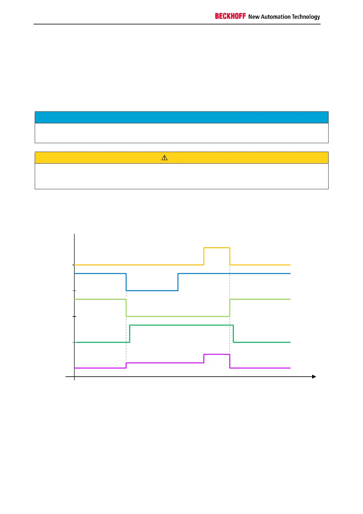
The following diagram shows the behavior when an emergency stop is triggered via Estop-In and
subsequent acknowledgement of the ESTOP function block via the Restart input. At least one of the EDM
inputs of the FB is active.
RESTART
Estop-In
EStopOut
EDM
FB State
State 1
State 3
State 6
State 1

 Loading...