Function blocks
Function blocks for TwinSAFE logic components 95
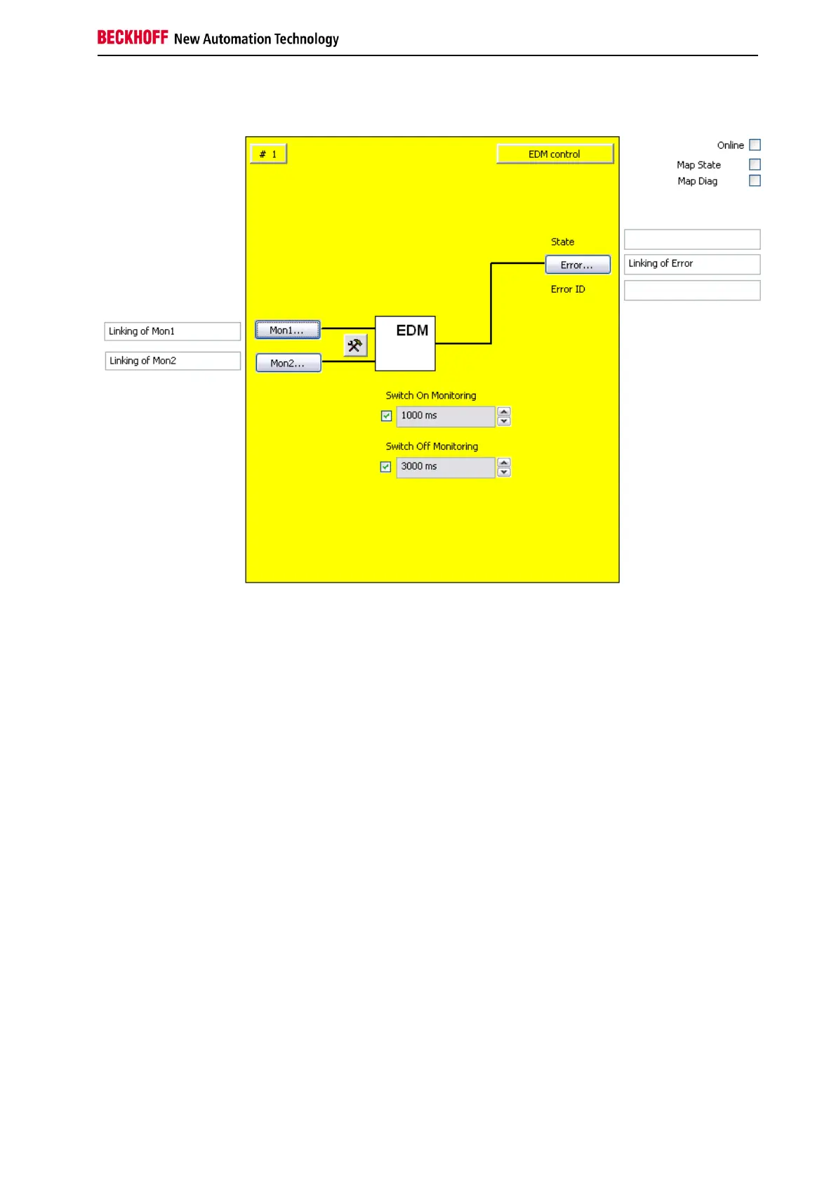
3.9.3 FB EDM configuration in the TwinCAT System Manager
Figure 3-43: FB EDM configuration
The FB EDM input variables are linked using the 'Mon1' and 'Mon2' buttons.
Use the Settings button to right or the two Mon inputs to configure them. Only single-channel evaluation is
available. In addition the inputs can be configured as make contact (NO) or break contact (NC). In the
default state all inputs are disabled.
Use the 'Switch-On Monitoring' and 'Switch-Off Monitoring' selection boxes to set the switch-on and
switch-off delay time. Use the checkboxes to the left of the text fields to activate the corresponding
monitoring time. Both are disabled in the default state.
Use the 'Error' button to transfer a function block error to the connected output variable. In online mode
the state and error IDs are filled with corresponding information.
The 'MapState' and 'MapDiag' checkboxes are used to specify which FB diagnostic functions are mapped
to the cyclic process image.

 Loading...